Attribute (dictionary item)
 Port check box cleared (a Part)
 Port check box selected (a Port)
For automation interface information about an Attribute, see
Attribute (automation interface).
Attributes are properties of Classes, Data Types, Interfaces and Signals that take values for particular object members of the class. Each Attribute should be elementary in the sense that it takes a single value for a particular object, or a group of values which belong together, for example address.
Attributes come to light naturally through Class Modeling, especially semantic modeling where the focus is on properties of classes. Again, as with Operations, it is important to allow the Class Model to stabilize before attempting to specify Attributes.
Attributes are specified in terms of semantics and data type. Semantics are specified in terms of a textual definition where this is not obvious from the name. Often a simple qualification is necessary. For example, Task Description is obvious but Task Price needs qualifying as "base price without unforeseen extras". In an object-oriented design data types are either predefined by the environment, such as Boolean or real, or are themselves classes or references to classes.
An Attribute can be shown on a Composite Structure Diagram as a part (Port check box cleared) or port (Port check box selected). For more information about parts and ports, see
Overview of parts, and
Overview of ports.
You can create an Attribute in the following ways:
• Through the context menu of a Class, Data Type, Interface or Signal: right-click the item, and select > .
• Through the context menu of a Package or the Model: right-click the item, and select > > > .
• Through the Attribute button on the Class Diagram tab.
• Through the Composite Aggregation tab button on a Class Diagram, but only when creating a part or port for a Class, Data Type, Interface or Signal that uses a Basic Type or Type Definition as its type.
• Through the Items tab of a Class', Data Type's, Interface's, Signal's Model's or Package's Property Pages.
In addition, you can also create an Attribute by copying an existing Attribute. Modeler copies the Attribute's links. For more information, see
Copying items.
You can use an Attribute to model a local or global constant. For more information, see
Creating a constant.
You can specify an Attribute's Type and Default through its signature. For more information, see
Using an attribute signature to specify properties. |
In the Packages and Parts pane, an Attribute's name is shown as follows:

On a Concurrency Diagram and Communication Diagram, the View Options allow you to either show or hide Attributes. On a Class Diagram, the View Options allow you to either show or hide:
• Public, Private, Protected and Package Attributes
• Access characters for Attributes
When used on a Class Diagram, an Attribute's notation is as follows.
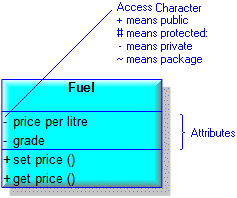
When an Attribute is derived, the name of the Attribute is prefixed by a slash mark.

Attributes (parts) of a Class, Data Type, Interfaces and Signals that use a Basic Type or Type Definition as a type can be shown as a link.

If the Attribute has Constraints applied to it, you can show the Constraints through the View Options of the Class – select the Show Constraints check box.
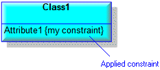
When used on a Composite Structure Diagram, a composite Attribute's (Part or Port) notation is as follows.
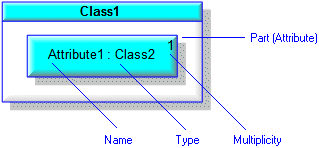
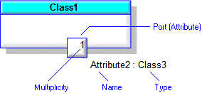
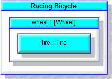
If a Part contains a Part that has had its Default Value changed in context, on a Composite Structure Diagram the type of the containing Part is shown in brackets. In the following example, the tire part in context has a Default Value that is different from the tire part on the type, that is, the Wheel Class.
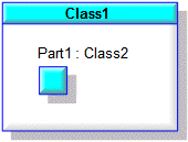
The View Options of a Part or Port allow you to snap a Part or Port inside the boundary, on the boundary or outside the boundary of the owning Part or Port. You can show a Part's Name and associated text outside of the Part through the View Options - select the Show Text As Floating Attachment check box.
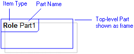
On a Composite Structure Diagram, top-level Parts can be shown as frames through the Part's View Options - select the Show As Frame check box.
For information about the View Options available for this symbol, see the following topics:
On an Activity Diagram, Input Pins and Output Pins can represent Attributes.
• On a Composite Structure Diagram, non-composite Part and Ports are shown with a dashed outline. To show Parts and Ports as top-level items, drag the Part or Port to free space on the diagram. • If a Part is shown out of context, its full containment path is shown. You can add or move a Part on a Composite Structure Diagram without rescoping it by holding down the Alt key whilst you drag the Part. |
When used on a Sequence Diagram, a composite Attribute's (Part or Port instance) notation is as follows.
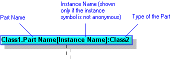
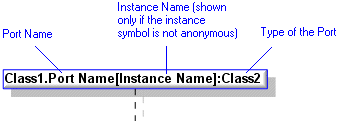
You add a Part or Port to a Sequence Diagram by dragging the item from a Modeler pane. Use the Parts pane to view Parts and Ports in context. |
In the Modeler panes, a short-cut symbol  on the Attribute's icon indicates that the item is a stub.
 on the Attribute's icon indicates that the item is a stub.
If you select the UML\Attributes folder in the Dictionary pane, the Contents pane displays the following information about each Attribute in the model: Name, Parent, Access, Unique, Storage, Changed By and Changed On. |
The following sections provide information about how an Attribute is used in the model. For more information about a property, item, model part or diagram, click it.
Properties
In addition to the standard properties an Attribute has these properties:
•
Behavior - applies only when the Attribute is a Port. (Is Behavior through the automation interface.)
•
Conjugated - applies only when the Attribute is a Port. (Is Conjugated through the automation interface)
•
Multiplicity (Multiplicity Text or Multiplicity Uml through the automation interface)
•
Service - applies only when the Attribute is a Port. (Is Service through the automation interface.)
•
Visibility (Access through the automation interface)
An instance of an Attribute (Part or Port instance on Sequence Diagram) can have these additional Properties:
Owned by
Owns
 Association - The Association is owned jointly by the Attribute and the other associated item. The access permissions you have to an Association are determined by the access permissions you have to the item at the start end of the Association.
 Dependency - The Dependency is owned jointly by the Attribute and the other associated item. The access permissions you have to a Dependency are determined by the access permissions of the dependent item.
Defined in these parts of the model
Used in:
Shown on these diagrams
 Communication Diagram - shown as Slot feature on Instance.
 Concurrency Diagram – shown on Classes, Data Types, Interfaces and Signals.
 Sequence Diagram – shown as Slot feature on Instance.
For information about how the View Options affect the presentation of Attributes, see the following topics:
Can be linked to these dictionary items
Can use these items as a data type
When an Attribute uses an item as a data type, Modeler creates a special link between the Attribute and the referenced item. You cannot navigate this link through the Links Editor. |
 Attribute
 Class
Class Data Type
 Interface
 Model
Model Package
 Role
Role Signal
 Comment
 Constraint
 IO Flow
 Class Model
 Class Diagram
 Composite Structure Diagram
 Variant Diagram
 Slot
Slot Stereotype
 Exception
 Type Definition