General flow diagram node (dictionary item)
|
|
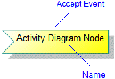
• In Studio 7.0 and earlier versions, General Flow Diagrams were named Activity Diagrams: If you created Activity Diagrams in Studio version 7.0 or earlier and have upgraded Modeler, your Activity Diagrams are now called General Flow Diagrams in Modeler
• Studio 7.1 included new Activity Diagrams, which you should use in preference to General Flow Diagrams. General Flow Diagrams are being deprecated and are included in Modeler only for backward compatibility.
• Should you need to create General Flow Diagrams, they can now be created only from the Model or a Package. After creating a General Flow Diagram you can drag it to an Activity, Actor, Class, Event, Operation, Subsystem or Use Case.
|
A General Flow Diagram Node appears on the General Flow Diagram. General Flow Diagram Nodes do not appear in the Modeler panes.
You can create a General Flow Diagram Node only through the General Flow Diagram. A General Flow Diagram Node can appear on only one General Flow Diagram, and a General Flow Diagram Node cannot exist unless it appears on a General Flow Diagram.
When used on a General Flow Diagram, a General Flow Diagram Node's notation is determined by its Node Type. The Node Type is initially set by the button or command you use to add the General Flow Diagram Node to the diagram. A General Flow Diagram Node is used for the following symbols:
• Accept Event
• Action
• Activity Final
• Decision
• Flow Final
• Fork
• Initial
• Object
• Send Signal
|
|
If an Activity Node crosses the border of a Swimlane, the Activity Node is owned by the Swimlane in which the top left corner of an Activity Node resides
|
You can link a General Flow Diagram Node to most dictionary item and diagram types in the Model by dragging the required item to the General Flow Diagram Node.
If you drag an item onto a General Flow Diagram, Modeler typically creates an Action Object that is linked to the item you dragged. The exceptions are as follows:
• If you drag an Event onto a General Flow Diagram, Modeler creates a Send Signal that is linked to the Event you dragged.
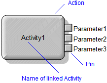
• If you drag an Activity on to a General Flow Diagram, Modeler creates an Action that is linked to the Activity you dragged. Modeler creates pins for the Activity's Parameters. You can use the Populate > Pins command on the context menu to add new Parameters that are added to a linked Activity.
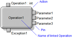
• If you drag an Operation onto a General Flow Diagram, Modeler creates an Action that is linked to the Operation you dragged. Modeler creates pins for the Operation's Return Type, Parameters and Exceptions.
• If you drag a State Diagram item onto a General Flow Diagram, Modeler creates an Object that is linked to the parent State Machine of the item you dragged. The Name of the Object is set to that of the parent State Machine. The State Diagram item you dragged is referenced in the Description of the Action Object through a Model Object Reference.
• If you link a Class to an Action, right-click the Action, and then select > ; Modeler creates a pin for each of the Class' Ports.
If you link a General Flow Diagram Node to an item and you select the General Flow Diagram Node on the General Flow Diagram, the Property Pages display properties of the linked item. If you want to view properties of the General Flow Diagram Node, right-click the General Flow Diagram Node, and then click Instance Properties.
|
|
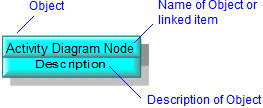
If both the Name and Description are displayed, the Name is displayed above the Description.
|
Accept Event
Represents a signal being received.
By default, the View Options show the Name of an Accept Event.
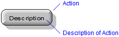
Action
Represents an action. Depending on what you are modeling, an action may be an Event, Operation or Use Case in the Model. You should link the Action to the item it represents.
By default, the View Options show only the Description of an Action. When you create an Action State, its Description is set to 'Description'.
If you drag an Activity on to a General Flow Diagram, Modeler creates an Action that is linked to the Activity you dragged. Modeler creates a pin for each of the Activity's Parameters. You can use the Populate Pins command on the context menu to add new Parameters that are added to a linked Activity.
If you drag an Operation onto a General Flow Diagram, Modeler creates an Action that is linked to the Operation you dragged. Modeler creates a pin for the Operation (if it has a return type), each Parameter and each linked Exception. An Action can also show a Class' Ports as pins. You can populate pins by right-clicking the Action, and then clicking Populate Pins:
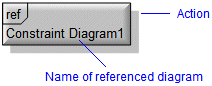
If you link a diagram to an Action, the appearance of the Action is as follows. You can open the diagram by right-clicking the Action, and then clicking Open:
Activity Final
An Activity Final indicates that an object ceases to exist.
By default, the View Options hide the Name and Description of an Activity Final.

For information about the View Options available for this symbol, see
Accept event view options - general flow diagram.
Decision
A Decision chains together multiple General Flow Diagram Flows. Use a Decision to construct complex transition paths between Actions. For example, to converge multiple incoming General Flow Diagram Flows into a single outgoing General Flow Diagram Flow, and to split an incoming General Flow Diagram Flow into multiple outgoing General Flow Diagram Flows with different guard conditions.
By default, the View Options hide the Name and Description of the Decision.

For information about the View Options available for this symbol, see
Decision view options - general flow diagram.
Flow Final
A Flow Final terminates a General Flow Diagram Flow.
By default, the View Options hide the Name and Description of a Flow Final.

For information about the View Options available for this symbol, see
Flow final view options - general flow diagram.
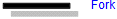
Fork
A Synchronization Bar splits or merges General Flow Diagram Flows.
By default, the View Options hide the Name and Description of a Fork.
For information about the View Options available for this symbol, see
Fork view options - general flow diagram.
Initial
An Initial indicates the point from which a General Flow Diagram Flow leads an object to the state it acquires at instantiation.
By default, the View Options hide the Name and Description of an Initial.

For information about the View Options available for this symbol, see
Initial view options - general flow diagram.
Object
Represents an object instance. You should link the Object to the item it represents.
If you drag an item (except an Operation) onto a General Flow Diagram, Modeler creates an Object that is linked to the item you dragged.
If you drag a State onto a General Flow Diagram, Modeler creates an Object that is linked to the State you dragged. The Name of the Object is set to that of the item that owns the State. The State is referenced in the Description of the Object through a Model Object Reference.
By default, the View Options show the Name and Description of an Object.
For information about the View Options available for this symbol, click here
Object view options - general flow diagram.
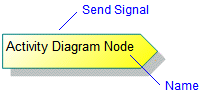
Send Signal
Represents a signal being sent.
If you drag an Event onto a General Flow Diagram, Modeler creates a Send Signal that is linked to the Event you dragged.
By default, the View Options show the Name of a Send Signal.
For information about the View Options available for this symbol, see
Send signal view options - general flow diagram.
The following sections provide information about how a General Flow Diagram Node is used in the model. For more information about a property, item, model part or diagram, click it.
Properties
A General Flow Diagram Node has these properties:
Owned by
 Swimlane
Owns
•
General Flow Diagram Flow —The General Flow Diagram Flow is owned jointly by the General Flow Diagram Node and the associated General Flow Diagram Node (if there is one)
Defined in these parts of the model
None. General Flow Diagrams are shown in the Miscellaneous folder of the Relationships pane.
Shown on these diagrams
 General Flow Diagram
 Variant Diagram
Can be linked to these dictionary items
• A General Flow Diagram Node can be linked to most dictionary item and diagram types in the Model.
 Stereotype