About the Creo Direct User Interface
The Creo Direct user interface, like that of Creo Parametric, consists of a main window with a status bar at the bottom. The status bar displays prompts, filter settings, and the mode for the modeling operation. Each object or a file in Creo Direct opens in its own window.
The design environment provides varying levels of detail to support the design process. You can use the following user interface items to work with a part or an assembly:
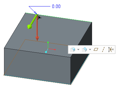
• A Live Toolbar with the most relevant tools (commands) for use on a selected entity. For example, if you select an edge, a Live Toolbar appears in the graphics window as shown in the following image:
• Options Toolbars with most relevant options for the selected tool (command). For example, if you click on the Live Toolbar (in the image above), the Options Toolbar for Round opens as shown below.
• Floating Dashboards with all the options for the selected tool (command). You can expand the Options Toolbar to open the Floating Dashboard.
• Keyboard and mouse shortcuts to save time and reduce the number of clicks.
• A dragger to modify data in the graphics window and view the results dynamically.
• A shortcut menu of frequently used commands appropriate to the current context.
The Live Toolbar and the Options Toolbar appear in the graphics window depending on the modeling context and the type of the selected entity. They enable quick and direct modification of geometry. Entities appear with distinct colors for visual feedback during various operations. During modeling operations such as propagating tangency, you can also preview geometric entities of a model in different colors. The use of color helps you understand how the model has been interpreted and what different conditions are applied to the entities.


