Highlights for other key enhancements:
Sketcher enhancements covered include the new diagnostic tools:
|
|
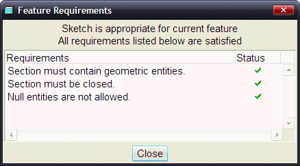
Shade Closed Loops and Highlight Open Ends are toggles, and will remember their setting for the duration of a Pro/ENGINEER session. Overlapping Geometry and Feature Requirements are operations for an on-demand check. All these commands can also be found under Sketch > Diagnostics. |


|
|
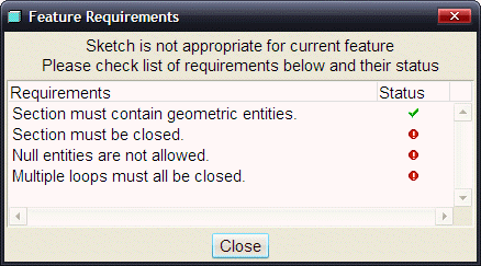
The status column of this report will show all green checks when the requirements for the feature type being created are satisfied. |
Select the Shade Closed Loop ![]() from the main toolbar at the top right of the screen.
from the main toolbar at the top right of the screen.
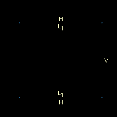
Using the Line Tool ![]() sketch another line to close off the shape that was sketched earlier.
sketch another line to close off the shape that was sketched earlier.
Choose the Select Tool ![]() or Click MMB.
or Click MMB.

Deselect the Shade Closed Loop ![]() , and the Highlight Open Ends
, and the Highlight Open Ends ![]() tools from the top toolbar, so they are no longer selected.
tools from the top toolbar, so they are no longer selected.
Using the Line Tool ![]() sketch another line intersecting the rectangular sketch created so far.
sketch another line intersecting the rectangular sketch created so far.
Choose the Select Tool ![]() or Click MMB.
or Click MMB.
Select the Overlapping Geometry Tool ![]() from the main toolbar at the top right of the screen and the entities in the sketch that are overlapping will be highlighted.
from the main toolbar at the top right of the screen and the entities in the sketch that are overlapping will be highlighted.

Select Complete Sketch ![]() from the Sketcher Toolbar.
from the Sketcher Toolbar.
Select Complete Feature ![]() from the dashboard, or MMB.
from the dashboard, or MMB.
Window > Close ![]() .
.
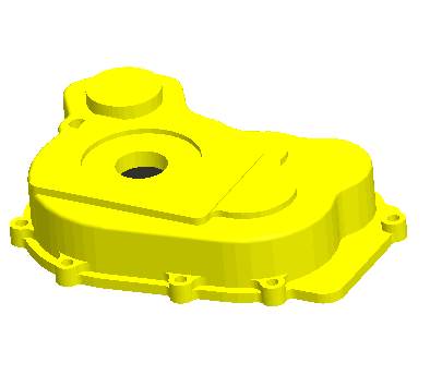
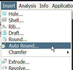
Auto Round is a new feature that intelligently rounds edges of a part. The Auto Round feature enables you to create round geometry of a constant radius on solid geometry or on a quilt of a part or assembly. The Auto Round Feature creates Round features called Auto Round Members (ARMs) and are represented on the Model Tree as subnodes of the Auto Round feature.
|
|
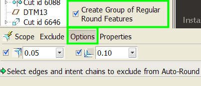
From the Options panel in the dashboard, you can choose to have a group of regular rounds created. |
|
|
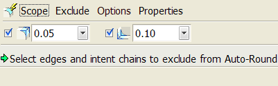
If the design intent is not to round all of the edges currently in the model, the autorounds can be applied to selected edges only, by using the Scope panel in the dashboard. As apparent in the message window shown above, it is also possible to select edges and intent chains to exclude. |
|
|
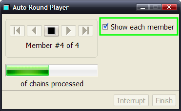
While Pro/ENGINEER is Auto Rounding the part, you can preview the rounds that are being created by selecting the "Show each member" check box in the Auto-Round player. |
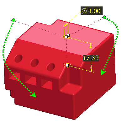
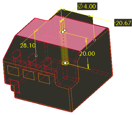
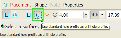
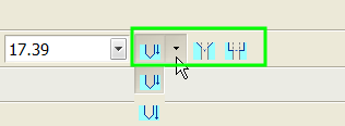
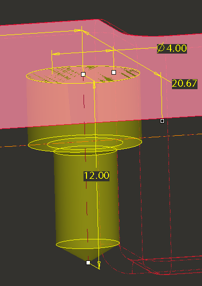
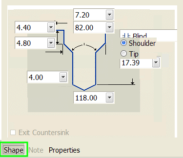
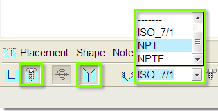
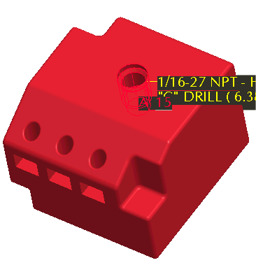
Enhancements to the Hole Tool include:

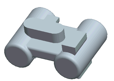
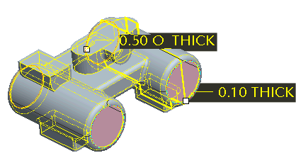
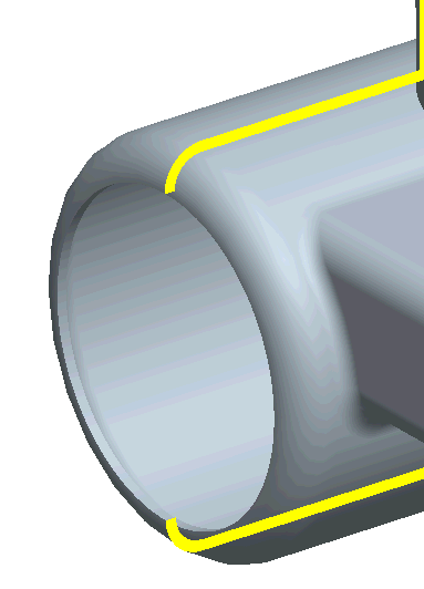
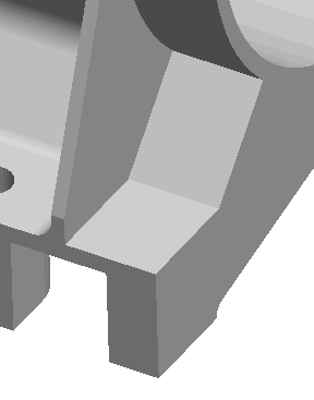
The Shell feature has been enhanced to allow a surface with neighboring tangent surfaces to be removed, and or have a different thickness value than the default. This improvement allows for greater flexibility when creating parts that need to be hollow.

|
|
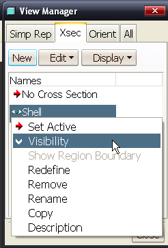
The cross-section will not update until the feature is completed. |
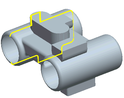
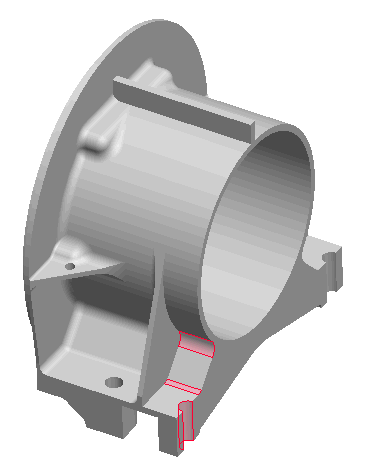
The new Remove Surface Tool can be used in many ways, including:
|
|
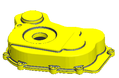
The geometry for this part was imported from a step file and is a single feature solid model that you will make modifications to. |
|
|
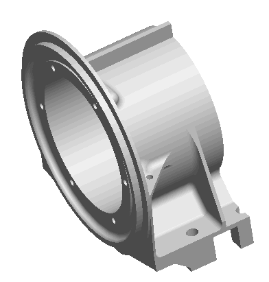
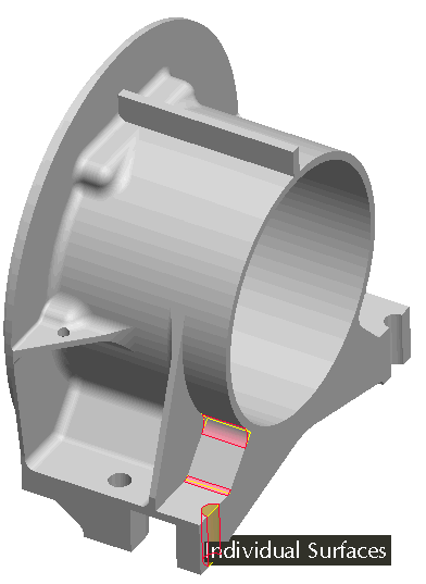
This tool requires an Object > Action workflow. All the powerful surface collections techniques are available, i.e., Seed & Boundaries. Once inside the tool, use References > Details... from dashboard to assist with selection process. |
|
|
Pro/ENGINEER creates the exported file based on PDF v1.6. Adobe Acrobat v7 and later support U3D graphics. |
Open ![]() engine.zip; double-click on ac-40.asm.
engine.zip; double-click on ac-40.asm.
File > Save a Copy...
Select U3D PDF (*.pdf) in the Type drop-down.
By default, the current object name appears in the New Name field.
Accept the default, or type a different name.
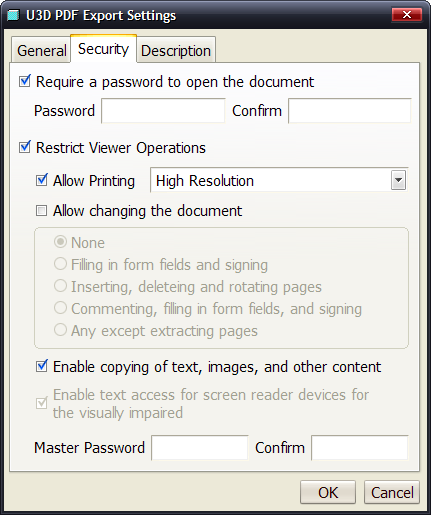
Click OK. The PDF Export Settings dialog box opens.
Click OK to complete the PDF export.
Adobe Reader 8 will start automatically and load your file!
Click the General tab and preview the options available.
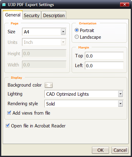
The Pro/ENGINEER model graphic is sized to fit on the selected page size, within the user-defined margins.
![]()
|
|
If you do not select Restrict Viewer Operations, anyone can print or copy from the document. To restrict high-resolution printing, change the option from the default, High Resolution, to Low Resolution. Certain options must be checked as pre-requisites to make sub-options available. |
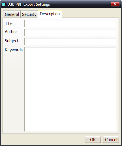
Type relevant document information in the following boxes:
Title, Author, Subject, and Keywords