Creo Elements/Direct Modeling allows you to move the faces of a part or recognized features almost without limits. You can move faces or features relative to other faces, move them along an axis, or rotate them around an axis. You can even use 3D Annotation dimensions if they reference the faces you want to move.
Depending on the face you use to select the feature, the system calculates which elements form the feature.
If you intend to move a face or recognized feature with blended edges, you must specify the blended edges you want redone. In this case, the blends are removed, the face or feature is moved, and the blends are recreated.
The figure shows an example of moving faces using a 3D Annotation distance dimension:
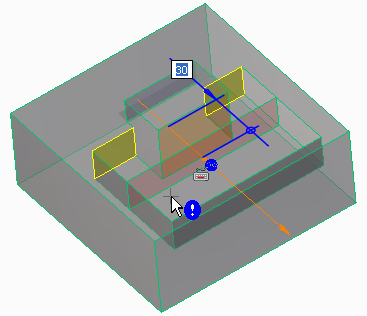
The figure shows an example of moving recognized features:
To move a face or recognized feature (boss or pocket),
1. Click Modeling and then, in the Modify 3D group, click the arrow next to Modify.
2. Click Move. The Move dialog box opens.
3. Select the face(s) or feature(s) to move:
◦ Click Faces and select a face that you want to move in the viewport. Press Shift to select multiple faces.
◦ Click Rec.Feat and select a feature in the viewport. Press Shift to select multiple features. You can set the following:
▪ Feat Select allows you to choose a type of feature.
You can choose any of the following recognized feature types:
• Automatic (selects the boss/pocket, rib, or slot with the smallest number of faces)
• Boss/Pocket
• Rib
• Slot
• Boss
• Pocket
• Composite Boss
• Composite Pocket
▪ Allow Face Splitting automatically splits faces if necessary to select the entire feature.
▪ To Part allows you to move a feature towards a part. This option is available only if the selected faces form a recognized feature.
4. Set the following options:
◦ Transform Objects: Allows you to position parts or assemblies without having to move the faces, when all faces of a part or all parts of an assembly are selected.
• Draw a box to select whole parts or whole assemblies.
• To select a part, as you draw the box, the cursor indicates whether complete or partial elements are selected. See
Boxing.
• You can also use the Select tool to select all the faces of a part or all the parts in an assembly. The highlight color of selected parts changes to dark blue. The highlight color of selected assemblies changes to cyan. You can change the default colors in
Modeling Settings.
Transform Objects is selected by default. To change the default setting, see
Change Modeling settings.
◦ Keep Tan: Preserve the tangential transitions between neighboring faces. Click Control to fix or unfix edges and faces. If you choose not to Keep Tan, smooth tangential transitions are replaced by edges.
◦ Redo Blend: Allow the operation to make automatic adjustments to blends. Click Control to specify the blends to redo.
◦ Extend allows you to extend a face or a recognized feature.
◦ Alternative Solution: Allows you to choose an alternative solution of the move operation. A warning is displayed if an alternative solution is not available. For example, if you move a face in such a way that it intersects with a geometric feature such as a boss, Creo Elements/Direct Modeling offers the following two alternative solutions:
▪ The moved face gets priority and extends through the boss (default solution in most cases).
▪ The existing model (boss) is retained and the moved face extends around the boss (default solution in some special cases in which, the original solution modifies the model heavily).
• While moving an element in the viewport, if the realistic feedback is displayed, use Alternative Solution to toggle between the two alternative solutions in the viewport.
• Even if you preview the changes, you can use Alternative Solution to toggle between the two alternative solutions in the viewport.
• If an alternative solution is available (indicated by appearing with the cursor in the viewport), press SPACEBAR and click on the Option Mini Toolbar (OMT) to toggle between the two alternative solutions in the viewport.
While moving an element in the viewport, if the quick feedback (Quick View mode) is displayed, the alternative solution is not displayed.
◦ Keep Feat allows you to keep the original feature when you move the feature. This option is available only if the selected faces form a recognized feature.
5. Move the face or feature. The 3D CoPilot snaps to any 3D object, 2D geometry, or construction geometry except a 2D spline.
When you move a face or a feature, you can use the Linear Bisector, Angular Bisector, or Line Between 2 Points command (on-the-fly) to draw bisectors, angle bisectors, or a line between two points (with a midpoint), and then use these lines as reference. You can use these commands only under certain conditions. For more information, see
Example: Move a face using a line between two points.
To use a linear bisector:
• Press X or,
• Right-click and choose Linear Bisector on the context menu or,
• Press SPACEBAR or the assigned key and click on the Option Mini Toolbar (OMT).
To use an angular bisector:
• Press Y or,
• Right-click and choose Angular Bisector on the context menu or,
• Press SPACEBAR or the assigned key and click on the OMT.
To create a temporary reference line between two points:
a. Press M, or right-click in the viewport and choose Line Between 2 Points on the context menu.
Alternatively, press SPACEBAR or the assigned key and click on the Option Mini Toolbar (OMT).
6. The Methods section under Position allows you to choose the type of positioning operation you want to perform:
◦ Dyn Pos: Move parts or assemblies in the viewport with on-screen tools that are appropriate for the type of object you select.
◦ Mate Align: Move parts into position with respect to another part. See the link below for more information.
◦ Two Points: Select two points in the viewport to move your part or assembly.
◦ Dimension: Allows you to move a face or feature by changing the value of a dimension created using 3D Documentation. See
Move a face using dimensions.
◦ Other: Restricts movement to the type of movement you select. Move the object in the viewport after you select one of the following options:
▪ Line/Axis: Move the object you select in the viewport in a linear direction.
▪ Plane: Move the object you select in the viewport anywhere on a plane.
▪ Plane by 3 Points: Move the object along a plane that you define by selecting three points on objects in the viewport. Only available if you use Selected.
▪ Rotate: Rotate the object you select in the viewport.
▪ Normal: Move the object you select in the viewport in the normal direction. This is a linear movement.
▪ Radial: Choose an axis. Specify a reference position toward which to move the object. When all reference positions are specified you can move the objects with the 3D Copilot or by typing in the offset value.
▪ Free: Drag the object you select anywhere in the viewport.
▪ Match 3 Points: Positions the object based on three points you select in the viewport.
▪ Pt Dir Pt: Positions the object based on a point, a direction, and another point that you select in the viewport.
▪ Pt Dir Dir: Positions the object based on a point, and two directions (along z axis and x axis) that you select in the viewport.
▪ By Ref CS: Positions the part based on a coordinate system.
◦ If you select Dyn Pos, Dimension, or one of the Other options, you may also choose some of the following options. Only the options that are appropriate for the type of positioning are available:
▪ Direction: Sets the direction to move the object. Click Direction and set a direction in the viewport. Press TAB to reverse the direction.
▪ Length: Type a value in this field to set the distance that the object is moved. You can also move the part in the viewport.
▪ Rot. Axis: Rotate the object along an axis you select in the viewport.
▪ Rot. Angle: First select Rot. Axis, then type a value in this field to set the angle that the object is moved.
▪ Fix Dir/Axis: Prevents the axis and direction from changing during positioning. Only allows you to rotate an object.
▪ Ang. by 2 Pts: First select a Rot. Axis, then you can use this method to rotate the part by selecting a start and end point.
▪ Center Axis: Sets the central axis for moving parts via the radial method.
▪ Radial Offset: The distance from the axis that the parts will move.
▪ Ref. Focus: Restricts the selection focus to the element type you select. This is helpful when you want to select a reference element in a complex area of the model.
▪ Values: All values you enter in the dialog will be considered absolute (based on the original position) or relative (based on the current position).
◦ If the Adv Assembly module is active, you will see the following options:
▪ Stop at Clash: Does not allow you to move an object so it occupies the same space as another object.
▪ Update Relations: All relation sets are solved immediately after you position an object.
▪ Keep in Active R-Set: Creates a new relation in the active relation set based on a Mate or Align operation.
▪ Physical: Simulates physical movement in the viewport. For example, if you drag an object, and it bumps into another object, it will go around the other object.
7. Click Preview to see the impact of changes before accepting them.
You can toggle between Realistic and Quick to see either realistic feedback or quick feedback while moving a face or a feature in the viewport. See
Realistic feedback.
8. The Upd Rels option is available when the Parametrics module is active. Select this option to update relations with your changes.
9. Click Next to finish the operation and move another face or recognized feature.
You can click Chk & Fix if you suspect a part is corrupt. Chk & Fix checks for self-intersections, knife edges, and void shells and attempts to fix them. If a part fails the check and fix, it is not modified and remains in its original state.
10. Click to complete the operation.
Limitations
• You can add or remove material. You can also remove edges and faces, but you cannot add them.
• Creo Elements/Direct Modeling prompts with an error message if it is unclear if you add or remove material. See the graphic below. You cannot move the face exactly on or beyond the meeting point of the extension lines.
• You cannot move a face if the other faces to grow were created with a freeform operation (unless they are cylindrical or planar), or if they were defined with a spline. Freeform and splinar faces generally cannot "grow", they can only "shrink".
• You can move a recognized feature within one face and onto other faces as often as you want. You can change the topology, add and delete faces, edges, and vertices. If you move the recognized feature to or beyond a face edge, and change the topology, it may lose its characteristics, and it is no longer recognized as a feature. Use the Undo function.
• If a group of faces is not recognized as a feature because it is embedded in more than one face, you can still move the group within limits. In the example below, you can select all the required faces by defining a feature or adding the faces to a list. You are allowed to move the boss along the edge it is sitting on, but because it is a list of faces (or defined feature), the boss has to stay embedded in the two faces it is embedded in now.
• You cannot move a face in its own plane.
• If you select the Redo Blend option, the system will attempt to recreate the blend with the same blending options. However, in some situations that may not be possible. If the blend was created with the RollAtSharp or RollAtSmooth options, the blend may be recreated without those options.
• If you use the Move 3D command on multiple parts, the successful operations are displayed as a partial result and the failures are displayed as labels (error feedback). The feedback labels are attached to the faces on which the operation has failed.
Limitations for Transform Objects
• Transform Objects is disabled if a configuration is active.
• If you select read-only parts or assemblies, a warning appears and the read-only elements are removed from the selection. The names of the read-only parts or assemblies are also listed in the output box.
• Any transformation (rotation and translation) of a part is allowed but it is checked for validity. An error message appears if the transformation is invalid. The validity depends on the selection and the move/stretch transformation. Whenever shared objects are selected using different paths, one of the selected shared objects is chosen. If this choice influences the result of the operation, then the transformation is invalid. If the result of the operation is independent of this choice, then the transformation is valid.
 Modify.
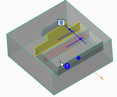
 appearing with the cursor in the viewport), press SPACEBAR and click
  on the Option Mini Toolbar (OMT).
 on the OMT.
 on the Option Mini Toolbar (OMT).
 to complete the operation.