Configuration diagram (ARINC for PikeOS code)

A Configuration Diagram is a hierarchical diagram representing all or part of an ARINC 653 configuration. It is based on the UML structure diagram which represents whole/part hierarchies using nested rectangles.
A Configuration Diagram allows you to create the items that define an ARINC configuration and application startup code.
When you create an Integration Project through the New > Integration Project command, the profile creates four Configuration Diagrams in the model:
• <module name> Configuration Diagram - This is the top-level Configuration Diagram that shows the owning Module and its moduleHM (Module HM Table), systemHM (System HM Table) and partHM (Partition HM Table) items. You can use this diagram to create and define the Partitions in your model.
The content of the following Configuration Diagrams could be shown on the preceding '<module name> Configuration Diagram' diagram, but it would make that diagram very cluttered.
• moduleHm Module HM Configuration Diagram1 - This Configuration Diagram shows the content of the moduleHM Module HM Table, that is, a System State Entry and default Error ID Actions. The content could be shown on the
• systemHm System HM Table Diagram - This Configuration Diagram shows the content of the systemHM System HM Table, that is, default System State Entries and Error ID Levels.
• partHm Partition HM Configuration Diagram1 - This Configuration Diagram shows the content of the partHM Partition HM Table, that is, a System State Entry and default Error ID Actions.
For more information about the preceding diagrams, click here
Diagrams and items created through the new > integration project command (ARINC for PikeOS code)" ?>.
Create a Configuration Diagram in the following ways:
• From a
Module: right-click the Module, point to ARINC 653, point to New, and then click Blank Configuration Diagram. This command creates an empty Configuration Diagram, onto which you can drag a Module, Partition, Module HM Table, Partition HM Table or System HM Table.
• From a
Partition: right-click the Partition, point to ARINC 653, point to New, and then click Partition Configuration Diagram. This command creates a Configuration Diagram with the Partition you right-clicked on the diagram.
• From a
Module HM Table: right-click the Module HM Table, point to ARINC 653, point to New, and then click Module HM Table Diagram. This command creates a Configuration Diagram with the Module HM Table you right-clicked on the diagram.
• From a
Partition HM Table: right-click the Partition HM Table, point to ARINC 653, point to New, and then click Partition HM Table Diagram. This command creates a Configuration Diagram with the Partition HM Table you right-clicked on the diagram.
• From a
System HM Table: right-click the System HM Table, point to ARINC 653, point to New, and then click System HM Table Diagram. This command creates a Configuration Diagram with the System HM Table you right-clicked on the diagram.
After creating a Configuration Diagram from an item, on a Configuration Diagram you can double-click that item to open its associated Configuration Diagram.
The following example shows item ownership on a Configuration Diagram.
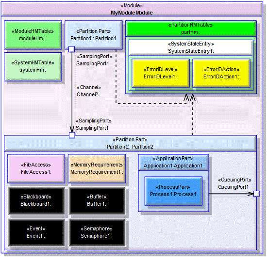
You can view all the Configuration Diagrams in the model through the Configuration Diagram folder in the ARINC 653 Profile pane.
A Configuration Diagram is based on a UML Composite Structure Diagram.
A Configuration Diagram can show the following items.
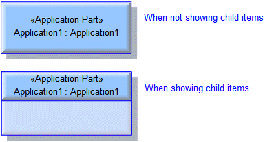
Create an Application Part through the diagram's tab: click the 

Application button, and then click within the owning Partition Part. When you create an Application Part, the profile creates an Application that types the Application Part and an Application Project.
Ensure that you link the Application Part to the appropriate Ports using a Port Usage link.
Specify the Application Project, CmdLine, ExecInPlace, FileName, HasEntryPoint, MaxChildTasks, MaxPrio, MaxThreads, PoolName, ResourceName, UsePool and VirtAddr properties for the Application Part through the Application that types it.

Create a Blackboard through the diagram's tab: click the 

Blackboard button, and then click within the owning Partition Part.
Specify the MaxMessageSize property of the Blackboard through the context menu of the Blackboard: right-click the Blackboard, point to ARINC 653, point to Set, and then click MaxMessageSize.

Create a Buffer through the diagram's tab: click the 

Buffer button, and then click within the owning Partition Part.
Specify the MaxMessageSize, MaxNbMessages and QueueingDiscipline properties of the Buffer through its context menu: right-click the Buffer, point to ARINC 653, point to Set, and then click the appropriate command.

Create a Channel through the diagram's tab: click the 

Channel button, click the starting Sampling Port or Queuing Port, and then click the ending Sampling Port or Queuing Port.
Dependency (UML item)

Create a Dependency between a Partition Part and its Partition HM Table: click the 

Dependency button, click the Partition Part, and then click the Partition HM Table.

Create an Error ID Action through the diagram's tab: click the 

Error ID Action button, and then click within the owning System State Entry.
Specify the Action property of the Error ID Action through the ErrorIDAction tab of the Error ID Action's Property Pages.

Create an Error ID Level through the diagram's tab: click the 

Error ID Level button, and then click the owning System State Entry.
Specify the ErrorCode and ErrorLevel properties of the Error ID Level through the ErrorIDLevel tab of the Error ID Level's Property Pages.

Create an Event through the diagram's tab: click the 

Event button, and then click within the owning Partition Part.

Create a File Access through the diagram's tab: click the 

File Access button, and then click within the owning Partition Part.
Specify the Execute, FileName, File Provider, Map, Read, Stat and Write properties of the File Access through its context menu: right-click the File Access, point to ARINC 653, point to Set, and then click the command for the property you want to set.

Create a Memory Requirement through the diagram's tab: click the 

Memory Requirement button, and then click within the owning Partition Part.
Specify the Access, Alignment, CacheMode, ContigMem, IsPool, PhysicalAddess, SizeBytes and Type properties of a Memory Requirement through its context menu: right-click the Memory Requirement, point to ARINC 653, point to Set, and then click the command for the property you want to set.
A Module cannot be created on a Configuration Diagrams, but you can drag a Module to a Configuration Diagram.
Specify the ModuleName and ModuleVersion properties of the Module through the Module tab of the Module's Property Pages.

Create a Module HM Table through the diagram's tab: click the 

Module Health Monitoring Table button, and then click within the owning Module.
You can create a Configuration Diagram from a Module HM Table: right-click the Module HM Table, point to ARINC 653, New, and then click Module HM Table Diagram. The profile adds the Module HM Table you right-clicked to the Configuration Diagram.
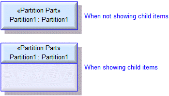
Create a Partition Part through the diagram's tab: click the 

Partition Part button, and then click within the owning Module. When you create a Partition Part, the profile creates a Partition item that types that Partition Part.
Ensure that you create a Dependency between the Partition Part and its Partition HM Table.
Specify the PartitionIdentifier and TimePartitionID properties of the Partition Part through the Partition Part tab of the Partition Part's Property Pages.
Specify the Duration, EntryPoint, HealthMonitorMode, MaxChildTasks, MaxPrio, NumFDs, PartitionStartupMode, Period, SystemPartition and TargetLanguage properties for the Partition Part through the associated Partition.
You can create a Configuration Diagram from a Partition (not a Partition Part): right-click the Partition, point to ARINC 653, New, and then click Partition Configuration Diagram. The profile adds the Partition you right-clicked to the Configuration Diagram.

Create a Partition HM Table through the diagram's tab: click the 

Partition Health Monitoring Table button, and then click within the owning Module.
You can create a Configuration Diagram from a Partition HM Table: right-click the Partition HM Table, point to ARINC 653, New, and then click Partition HM Table Diagram. The profile adds the Partition HM Table you right-clicked to the Configuration Diagram.

Create a Port Usage (UML Association) through the diagram's tab: click the 

Port Usage button, and then click the following items:
• The Destination Queuing Port or Destination Sampling Port on a Partition Part, and then an Application Part within that Partition Part.
• The Application Part within a Partition Part, and then the Source Queuing Port or Source Sampling Port on that Partition Part.

Create a Process Part through the diagram's tab: click the 

Process Part button, and then click within the owning Application Part. When you create a Process Part, the profile creates a Process item that types the Process Part. The Process is created in the associated Application Project.
Specify the BasePriority, Deadline, EntryPoint, Period, StackSize and TimeCapacity properties of the associated Process.

Create a Source Queuing Port through the diagram's tab: click the 

Source Queuing Port button, and then click within the owning Partition Part.
Create a Destination Queuing Port through the diagram's tab: click the 

Destination Queuing Port button, and then click within the owning Partition Part.
Specify the Direction, MaxMessageSize, MaxNbMessages and QueuingDiscipline properties through the context menu of the Queuing Port: right-click the Queuing Port, point to ARINC 653, point to Set, and then click the command for the property you want to set.

Create a Source Sampling Port through the diagram's tab: click the 

Source Sampling Port tab button, and then click within the owning Partition Part.
Create a Destination Sampling Port through the diagram's tab: click the 

Destination Sampling Port tab button, and then click within the owning Partition Part.
Specify the Direction, MaxMessageSize and RefreshRateSeconds properties through the context menu of the Sampling Port: right-click the Sampling Port, point to ARINC 653, point to Set, and then click the command for the property you want to set.

Create a Semaphore through the diagram's tab: click the 

Semaphore tab button, and then click within the owning Partition Part.
Specify the CurrentValue, MaxValue and QueueingDiscipline properties through the context menu of the Semaphore: right-click the Semaphore, point to ARINC 653, point to Set, and then click the command associated with the property you want to set.
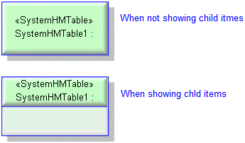
Create a System HM Table through the diagram's : click the 

System Health Monitoring Table button, and then click within the owning Module.
You can create a Configuration Diagram from a System HM Table: right-click the System HM Table, point to ARINC 653, point to New, and then click System HM Table Diagram. The profile adds the System HM Table you right-clicked to the Configuration Diagram.
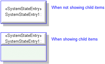
Create a System State Entry through the diagram's tab: click the 

System State Entry button, and then click within the owning Module HM Table, Partition HM Table or System HM Table.
The following sections provide information about how a Configuration Diagram is used in the model.
Create Configuration Diagram from
Creates or shows these ARINC items
•  Dependency (UML item)
 Dependency (UML item)
)
ARINC properties
None.


