Workflow to Manually Designate Components and Route Cables
Prior to routing a wire, cable, or sheath, you must define or read in the spool files for each of them. For more information, see topics Creating Spools and Modifying Spools.
The workflow for manually designating components and routing cables is as follows:
1. Manually Designate the Components
a. Click  Cabling Data >
  .
.
Cabling Data > .b. Select the component that you want to designate as connector.
2. Select the coordinate system that you want to assign as entry ports to carry the cable and wire on the connector in the Entry Ports table.
a. In the Entry Port Name column select the coordinate system on the connector.
b. Switch the value from FALSE to TRUE in the Designated Entry Port column.
c. Select a port type in the Type column.
▪ Wire allows to route a single wire. You cannot route a cable or multiple wires to a wire entry port.
▪ Round and Flat allows multiple connections. A ribbon cable is routed to a flat entry port.
d. Set Internal Length.
e. Click Apply to designate the connector.
3. Designate all components as connectors in the cabling assembly.
4. Route wires and cables through entry ports on the connectors.
Example
Refer the cabling_assembly.asm sample assembly to learn how to manually designate components and auto route cables through the entry ports of the connectors. Sample models are available here. Open cabling_assembly.asm. Select MANUAL_ROUTE from the  Saved Orientations list. Set MANUAL-ROUTING as the working harness.
Saved Orientations list. Set MANUAL-ROUTING as the working harness.1. Click Cabling Data >
Cabling Data > 2. Select the component to designate as shown in the figure. The component name and Reference Designation appears in the table.
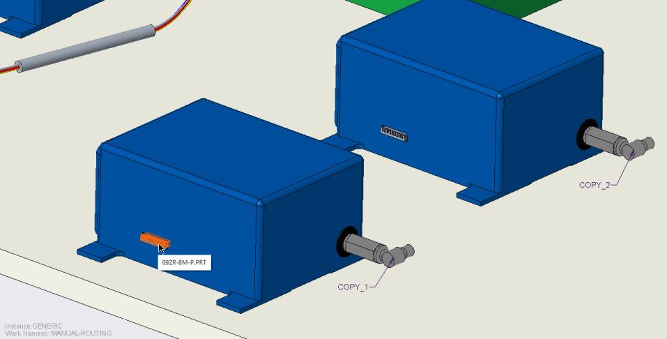
3. To designate an entry port, expand the Entry Ports table.
4. To designate 09ZR-8M-P, switch the value from FALSE to TRUE in the Designated Entry Port column. Select the Type and define the Internal Length, if required.
5. Click Apply. The connector is designated.
6. Follow steps 1 – 5 to designate the other component shown in the figure.
7. Click  Route Cables to open the Route Cables dialog box.
Route Cables to open the Route Cables dialog box.8. Click No in the Component Designation message box.
9. In the Route Cables dialog box, click  to route a wire.
to route a wire.Ensure that the spools have been read in before you start routing wires and cables. |
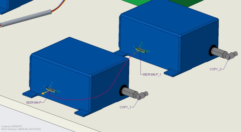
10. Select the first connector from the graphics window. The SEL ENTRYPRT menu appears.
11. Click ENTRY and Done Sel to specify the From location.
12. Select the other connector from the graphics window. The SEL ENTRYPRT menu appears.
13. Click ENTRY and Done Sel to specify the To location.
14. Click Apply. The wire is routed through the entry ports of the two connectors.
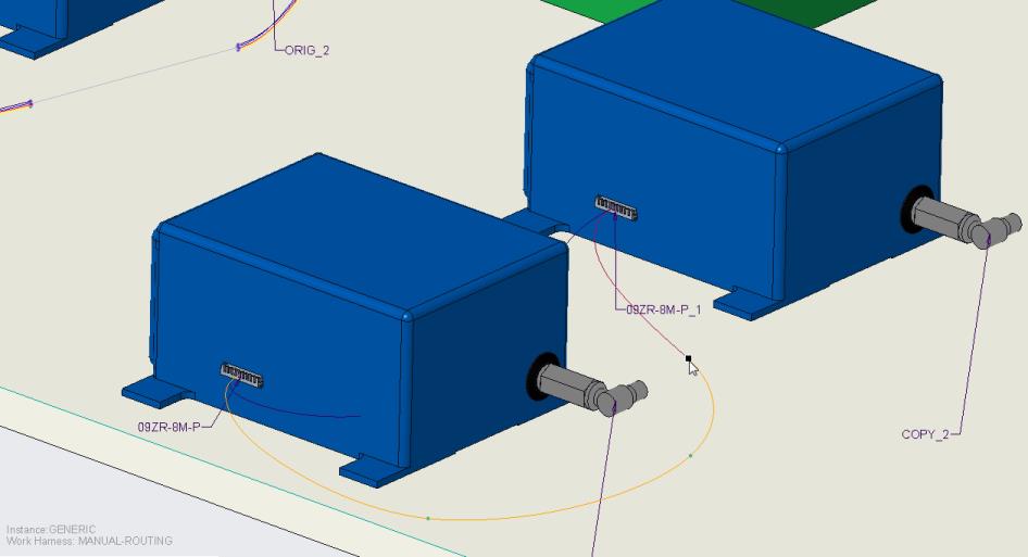
15. Click Location. The Location tab opens.
16. Click in the graphics window to add locations as shown in the figure, and then click OK.
To Undesignate a Connector
1. Right click the connector and select  Undesignate.
Undesignate.2. The component is no longer designated as a connector.