Creating Spools
A spool defines parameters for wires, cables, sheaths or some cosmetics elements. Cabling uses spool information to create and regenerate the 3D graphical representation.
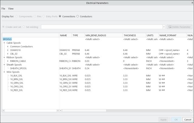
Before routing, make sure you have an available spool. Use the Electrical Parameters dialog box to create and modify spools. Updates to spool parameters after routing are reflected in the 3D graphical model after regeneration.
Spool Parameters
The following table lists all system spool parameters. The table also lists which parameter is required, optional, and recommended for the specific type of spool. You can also add a user defined parameter to define specific requirements.
• R=Required
• O=Optional
• RD=Recommended
|
Parameters
|
Description
|
Wire
|
Cable
|
Cable Conductor
|
Sheath
|
Cosmetic
|
Marker
|
Tie-wrap
|
|---|---|---|---|---|---|---|---|---|
|
NAME
|
Name of the spool.
|
R
|
R
|
R
|
||||
|
TYPE
|
The type of spool.
|
WIRE
|
PREFAB
|
SHEATH
|
MARKER
|
|||
|
SHEATH_TYPE
|
Specifies the type of sheathing for this spool. Valid values are TAPE, TUBE, and SHRINK
|
R
|
||||||
|
PN
|
The customer (user) Part Number
|
R
|
R
|
R
|
R
|
R
|
R
|
R
|
|
MANUFACTURER
|
Name of the supplier.
|
R
|
R
|
R
|
R
|
R
|
R
|
R
|
|
MANUFACTURER_PN
|
The part number issued by the manufacturer.
|
R
|
R
|
R
|
R
|
|||
|
MIN_BEND_RADIUS
|
Sets the minimum bend radius that the cable or sheath can take when it is routed.
When used with the DEFINE and ENDDEF cable spool parameters to define a conductor, the value of this parameter overrides the DEFAULT_COND_BEND_RAD parameter value.
|
R
|
R
|
O
|
O
|
|||
|
THICKNESS
|
The diameter of the WIRE or ROUND type cable and the thickness of the FLAT type cable.
This value is utilized to offset the centerline of the cable from the surfaces when you place a location.
When used with the DEFINE and ENDDEF cable spool parameters to define a conductor, the value of this parameter overrides the DEFAULT_COND_THICKNESS parameter value.
|
R
|
R
|
O
|
||||
|
UNITS
|
Sets the units for the thickness of the spool, for example, millimeter , foot, or inch.
|
R
|
R
|
R
|
R
|
|||
|
NUM_CONDUCTORS
|
The total number of conductors present in a cable.
|
R
|
||||||
|
COLOR
|
Establishes the color of the cable, wire insulation, or sheathing. The value for this parameter must map to the name of a color in the Appearances Manager.
|
RD
|
RD
|
RD
|
RD
|
|||
|
DENSITY
|
Linear density, mass per unit length. The MASS_UNITS and UNITS parameters should also be specified for the wire, cable, or sheath.
If you do not use the MASS_UNITS and UNITS parameters, the default units for the value of the DENSITY parameter are derived from the assembly.
|
RD
|
RD
|
RD
|
RD
|
|||
|
MASS_UNITS
|
The mass units for example, ounce, pound, or kilogram. Specify this parameter when the DENSITY parameter is used.
|
RD
|
RD
|
RD
|
RD
|
|||
|
OUTER_DIAMETER
|
Indicates the outer diameter of the tube sheathing. The units used are specified by the UNITS parameter.
|
R
|
||||||
|
PRESHRINK_INNER_DIAMETER
|
Indicates the pre-shrunk diameter of SHRINK sheathing. This value specifies the inner diameter only and allows the system to check interference between the shrink sheathing itself and the wires, cables, and bundles within it. The thickness of sheathing is specified by the parameter WALL_THICKNESS. A value of 0 (default) forces the SYSTEM to NOT check for any interference.
|
R
|
||||||
|
SHEATH_TYPE
|
Specifies the type of sheathing for this spool. Valid values are TAPE, TUBE, and SHRINK
|
R
|
||||||
|
WALL_THICKNESS
|
Indicates the thickness of the sheathing. The units used are specified by the UNITS parameter.
|
R
|
||||||
|
Optional Parameters
|
||||||||
|
DEFAULT_COND_BEND_RAD
|
Sets the default minimum bend radius for all conductors in the cable. The value of this parameter can be overridden by specifying a value for the MIN_BEND_RADIUS spool parameter in the conductor definition.
|
O
|
||||||
|
DEFAULT_COND_THICKNESS
|
Sets the default thickness for all conductors in a cable. The value of this parameter can be overridden by specifying a value for the THICKNESS spool parameter in the conductor definition.
|
O
|
||||||
|
COLOR_CODE
|
Establishes the code of the color
|
O
|
O
|
O
|
O
|
|||
|
INSUL_TYPE
|
Describes the insulation type, such as, fiber, teflon, or tefzel.
|
O
|
O
|
O
|
||||
|
LINEAR_RESISTANCE
|
Sets the linear resistance for the spool.
|
O
|
O
|
|||||
|
LINESTYLE
|
Changes the line style for cable or sheath spools. If you set this parameter for a sheath spool, the line styles assigned to a bundle overrides this parameter value. The following line styles are permitted: SOLID FONT (default), DOTFONT, CTRLFONT, PHANTOMFONT, DASHFONT, CTRLFONT_S_L, CTRLFONT_L_L, CTRLFONT_S_S
|
O
|
O
|
O
|
||||
|
OUTER_SHIELD_LINEAR_RESISTANCE
|
Specifies linear resistance of the wire's outer shielding.
|
O
|
||||||
|
SHIELD_TYPE
|
A text string indicating cable shield type.
|
O
|
||||||
|
SHIELD_LINEAR_RESISTANCE
|
Specifies linear resistance of the wire's shielding.
|
O
|
||||||
|
CABLE_JACKET_REPORT_NAME
|
Use the default value DEFAULT, in which case the name of the cable shows in the report table. Any other value is interpreted as plain text. For example, &cable_name has no special meaning.
|
O
|
||||||
|
CABLE_SHIELD_REPORT_NAME
|
Use this name for the cable symbol if the cable is shielded.
|
O
|
||||||
|
LIN_CAP_TO_ITEM
|
Specifies linear electric capacity between items.
|
O
|
||||||
|
LIN_CAP_ITEM_TO_SHIELD
|
Specifies linear electric capacity between items and shield.
|
O
|
||||||
|
LIN_CAP_ASSEM_ITEM_TO_SHIELD
|
Specifies linear electric capacity between assembly items and shield.
|
O
|
||||||
|
OUTER_SHIELD_THICKNESS
|
Specifies thickness of the outer shielding of the wire.
|
O
|
||||||
|
WIRE_CONSTRUCTION
|
As a text string indicates wire construction, that is, solid, stranded, and so on.
|
|||||||
|
WIRE_GAUGE
|
As a text string indicates wire gauge.
|
O
|
O
|
|||||
|
WIDTH
|
Specifies the tape width for tape sheathing.
|
Ribbon Cable Only
|
||||||
Creating a Spool
Follow these steps to create a spool:
1. Select  Create Spool from the
  Spools drop down list. The Create Spool dialog box opens.
Create Spool from the Spools drop down list. The Create Spool dialog box opens.2. In the Create Spool dialog box, perform the following:
◦ Select the spool type.
◦ Enter the File name and Common name. The spool name must be unique.
◦ Click Create to create a spool in the current session or click Create & Add to create and add the spool to the harness.
3. Use the Electrical Parameters dialog box, to add or modify parameters, and then click Apply.
4. To add parameters that are not available by default, click > . The Model Tree Columns dialog box opens.
a. Select the required parameter under Not Displayed. If you want to add user-defined parameters, type the name of the parameter in the Name box.
b. Click  to add the parameter to the Displayed list.
to add the parameter to the Displayed list.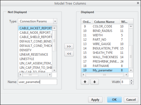
c. Click OK to add the selected parameter to the Electrical Parameters dialog box.
5. Click OK in the Electrical Parameters dialog box. A new spool is created.
Saving the top-level assembly design saves all spools in the working directory. Click Save in the Electrical Parameters dialog box and select a save location. All spool files are saved with the *.prt extension. |
Customizing the Display of Spool Parameters in the Spool Library
The Spools Library supports parameter display using a .lst file. You can define which parameters appear and in what order by creating or editing the spool_index.lst file in the Spools Library directory. This file is automatically created in the working directory or in the Spool directory if the pro_spool_dir configuration option is set.
This enhancement improves usability and provides greater control over how spool data is presented.
To customize the display of parameters in the spool library, do the following:
1. Open the spool_index.lst file in a text editor.
2. Edit the second row to add or reorder parameter names, except for the first three (NAME, TYPE, SHEATH_TYPE). These are mandatory and cannot be removed or reordered.
3. Save the file and refresh the spool directory.