Designating Connectors
An assembly component must be designated as a connector before you use it as a connector. This makes the component eligible to carry pin and entry port information for starting and ending cables.
If you are using a logical reference from a Diagramming file, you can use the model_name diagram connector parameter to automatically designate specific components as connectors. After the part is designated, you can route wires or cables to it.
You can auto designate or manually designate component as connectors. You can change the designation of a connector by designating it again or by modifying it. You can also undesignate a connector. When you undesignate a connector, you must strip it of all connector data.
Use  Designate and
  Undesignate to replace all information in the connector parameters.
Designate and Undesignate to replace all information in the connector parameters.Autodesignating Components as Connectors
If the Cabling assembly has a logical reference to a diagram file or an XML file, you can automatically designate a component in the assembly as a connector. Automatic designation of a component as a connector is possible only when the corresponding connector in the diagram file or the XML file has the <model_name nnn> parameter associated with it. In this parameter, nnn is the model name of the 3D part in the Cabling assembly that you want to represent as the connector.
If you have not set the model_name parameter in your logical reference, you can use  to match assembly components to connectors from the logical reference.
to match assembly components to connectors from the logical reference.In an XML file, the assembly can have a group-block-port structure instead of a group-port structure. A group-block-port structure has subconnectors with ports within a parent connector with ports.
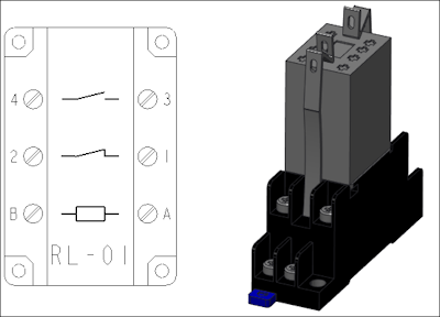
An assembly with a group-port structure is shown in the following figure:
An assembly with a group-block-port structure with L1 and L2 as subconnectors and L3 as parent connector is shown in the following figure:
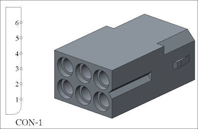
L1 has two ports named P1 and P2. L2 has two ports named P3 and P4. L3 has two ports named P5 and P6.
If you want to reassign the ports or pins of subconnectors to their parent connector and remove the subconnectors, use the Collapse Sub-Connectors option.