
Assembly of Reference Model and Workpiece
At this stage we need to define what part we want milled and assemble it in as well as define the workpiece.
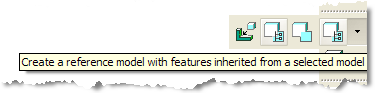
1. Click on the flyout for the Assemble a Reference Model ![]() icon. Click on the Create a reference model with features inherited from selected model
icon. Click on the Create a reference model with features inherited from selected model ![]() icon.
icon.
2. Select the core.prt and select Open.
|
|
Component Interfaces are used to make the assembly process easier for this step. |
3. Click on the Datum Plane ![]() icon from the Main toolbar. We will use planes as assembly references for the next step.
icon from the Main toolbar. We will use planes as assembly references for the next step.
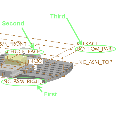
4. Select NC_ASM_RIGHT plane first, CHUCK_FACE plane and BOTTOM_PART plane last in that exact order as shown below.
5. Select Apply ![]() from the dashboard.
from the dashboard.
6. Click on OK from the Create reference Model Window.
7. Select OK from the Warning Message Window. This is to confirm the change of accuracy to match the Assembly Accuracy.
8. Click on the Datum Plane ![]() icon from the Main toolbar to blank the Datum Planes.
icon from the Main toolbar to blank the Datum Planes.
Creating Workpiece
9. Select the Create Auto-Workpiece ![]() icon from the toolbar on the right hand side. This uses the default CSYS from the Fixture.
icon from the toolbar on the right hand side. This uses the default CSYS from the Fixture.
10. Select the ![]() ZERO from the Model Tree. This aligns the Workpiece to the CSYS.
ZERO from the Model Tree. This aligns the Workpiece to the CSYS.
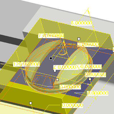
11. Adjust the workpiece by dragging the handles in white directly from the model. Drag the middle (Z+ direction) about 5 mm upwards.
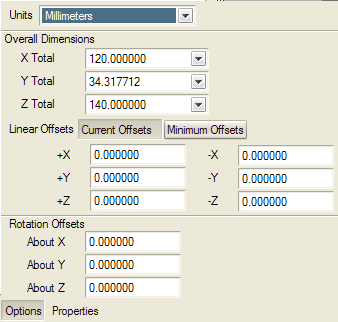
Alternatively, select Options from the Dashboard and enter 5 in the +Z box.
12. Select Apply ![]() from the dashboard.
from the dashboard.