Manufacturing
Enhancements covered in this Tutorial:
Other key enhancements to Manufacturing Solutions:
- Manufacturing & Tooling UI Modernization
- New UI for turn profile (dashboard)
- Improved workflow (removal of some of the "side" menus)
- Modern NC parameter UI
- Improvements to Process Manager
- Support for Roughing, Re-Roughing, Finishing and Corner Machining
- 3 Axis Trajectory with Customize
- Improved Surface Finish
- Holder Degouging
- New Corner Machining
- Direct Nurbs Output
- Color Mold Splitting
- Pro/CMM
- Leverages Pro/NC user Model
- Support of non-measured entities
- Support for scanning
|

|
May 16, 2007 - PTC Aquires NC Graphics! Read more here: http://www.ptc.com/company/ncgraphics/index.htm
NC Graphics delivers best-of-breed software for optimizing tool making and high-speed precision machining processes to more than 1,500 customers in multiple discrete manufacturing vertical markets such as aerospace, automotive, medical equipment and motorsports. With this acquisition, PTC strengthens the link between product design and manufacturing, offering our customers faster production of molds and dies. |

Manufacturing Ease-of-Use
This Tutorial will go through the basic Manufacturing workflow:
- Manufacturing start part
- Reference model definition
- Workpiece definition
- Operation definition
- Toolpath definition
1. Set Working Directory to MFG_UI
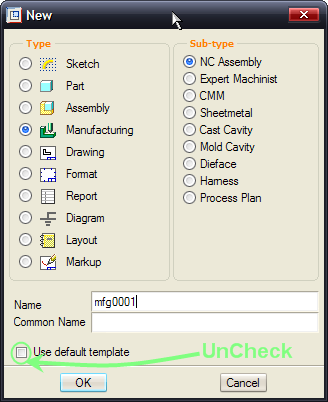
2. Select New Object  from the main toolbar.
3. Select Manufacturing from the Type list. Ensure that Use Default Template is Unchecked and click OK.
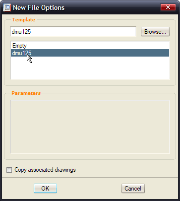
4. Select dmu125 from the Template List and click OK.
|
|
The Manufacturing Template is useful as it will have the Machine, Fixture and Operation pre-defined. In this case it is a 3-axis mill that we will use to machine a core from a mold. This ability is also available in Wildfire 3.0. |
Assembly of Reference Model and Workpiece
At this stage we need to define what part we want milled and assemble it in as well as define the workpiece.
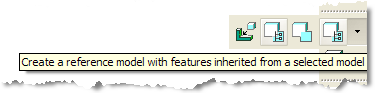
1. Click on the flyout for the Assemble a Reference Model  icon. Click on the Create a reference model with features inherited from selected model
  icon.
icon.
2. Select the core.prt and select Open.
|

|
Component Interfaces are used to make the assembly process easier for this step. |
3. Click on the Datum Plane  icon from the Main toolbar. We will use planes as assembly references for the next step.
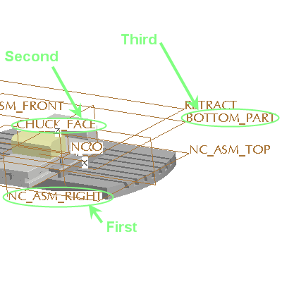
4. Select NC_ASM_RIGHT plane first, CHUCK_FACE plane and BOTTOM_PART plane last in that exact order as shown below.
5. Select Apply  from the dashboard.
6. Click on OK from the Create reference Model Window.
7. Select OK from the Warning Message Window. This is to confirm the change of accuracy to match the Assembly Accuracy.
8. Click on the Datum Plane icon from the Main toolbar to blank the Datum Planes.
Creating Workpiece
9. Select the Create Auto-Workpiece  icon from the toolbar on the right hand side. This uses the default CSYS from the Fixture.
10. Select the  ZERO from the Model Tree. This aligns the Workpiece to the CSYS.
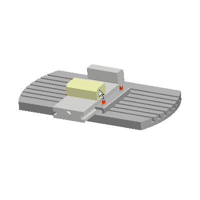
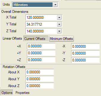
11. Adjust the workpiece by dragging the handles in white directly from the model. Drag the middle (Z+ direction) about 5 mm upwards.
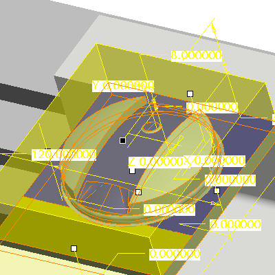
Alternatively, select Options from the Dashboard and enter 5 in the +Z box.
12. Select Apply  from the dashboard.
Toolpath Creation
At this point we will create the toolpath from pre-defined templates using the Process Manager.
First, we need to define a Mill Window to define what to machine.
1. Click on the Mill Window Tool  icon from the right-hand toolbar.
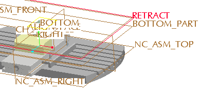
2. Select the "Retract" plane from the Model Tree. This creates a mill window on the retract plane by taking the outline of the workpiece.
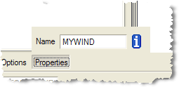
3. Select Properties from the dashboard and rename the Mill Window to MYWIND.
4. Select Apply from the dashboard.
|
|
This is the default setting but other techniques exist to create Mill Windows such as Sketching or selecting edges. |
Now we have all the settings necessary to define a toolpath.
1. Select the Process Manager  icon from the main toolbar.
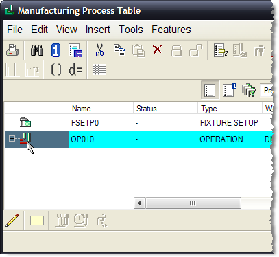
2. Select the OP010 by selecting the icon to the left of the operation as shown above.
3. Select the Insert New Steps From Template  icon.
icon.
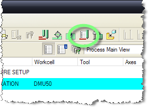
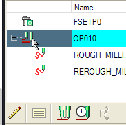
4. Select the basic_roughing.xml template > Open.
Notice that there are 2 sequences, roughing and re-roughing.
|
|
The template is looking for specific references such as the RETRACT Plane and the MYWIND Mill Window. This is the reason behind renaming the Mill Window to the proper name. If not you will be prompted to select a Mill Window manually. |
5 Click on the Apply from the bottom toolbar of the Manufacturing Process Table. The toolpath is completed.
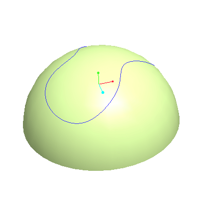
6. Select the Operation by clicking the icon to the left of OP010 as shown below.
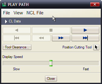
7. Click on the Show Toolpath  icon to play the path.
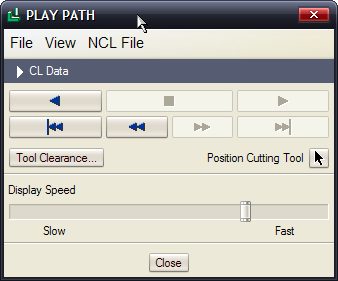
8. Click on Play  from the Play Path Window. Select Close when done.
9. Select Window > Close.
You have completed this tutorial.
Machine Kinematic Simulation
Machine kinematics for Pro/NC is a new capability that enables the simulation of the NCL tool path with an actual machine.
Some features include:
- Dynamic Collision detection with the solid tool, holder, and fixture
- Stop at collision
- Available for both Milling and Turning
In this exercise you will setup a 5-axis laser cutter NC machine and simulate a tool path.
1. Set Working Directory to MFG_MKS
2. Open  LASER_TEST.MFG
3. RMB on Trajectory Milling from the Model Tree and choose PlayPath.
4. Play Forward  and adjust the speed as necessary. Close when done.
Creating the Machine
Now we will build the 5-Axis LaserDyne Machine that will simulate the Cutter Location (NCL) toolpath from the previous page.
1. Open the LASERDYNE_5AX.ASM assembly.
In this case, the X,Y,Z and C Axes are already defined as parts with mechanism constraints. We need to define the D Axis that will hold the tool.
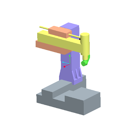
2. Move the machine as a regular mechanism by using the Drag Packaged Components tool  .
.
3. Pick anywhere on the yellow (yaxis.prt) part, then drag around with mouse. Close the Drag dialog box when done.
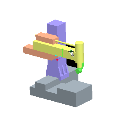
4. Select Add Component  and assemble daxis.prt.
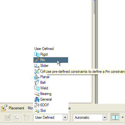
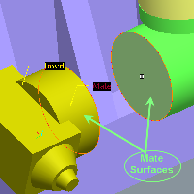
5. Change the constraint type from User Defined to Pin  .
.
6. Select the cylindrical surface from both the caxis part and daxis part as shown.
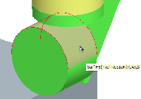
7. Select the 2 planar surfaces for a Mate. Ensure the Mate is Coincident by selecting the Position Coincident  icon from the Position drop down list in the dashboard.
8. Click  on the dashboard to finish the operation.
The machine is complete! Feel free to move it using the Drag Packaged Components tool from the main toolbar.
Simulation Setup
At this point we are ready to setup the tool path simulation.
1. Close the LASERDYNE_5AX.asm Window by WINDOW > Close.
2. Return to LASER_TEST.MFG by Window > LASER_TEST.MFG from the main menubar.
3. RMB on MACH01 from the Model Tree and select Edit Definition.
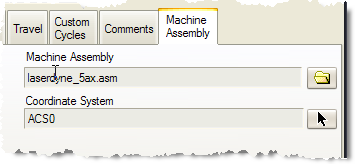
4. Select the Machine Assembly tab.
5. For the Machine Assembly select Open and select the laserdyne_5ax.asm assembly and OK.
6. For the Coordinate System select  and pick the ACSO Coordinate System for the Model Tree and OK.
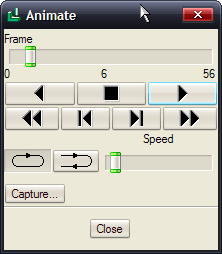
7. RMB on Trajectory Milling and Select Machine Play.
8. Select Play from the Animate Dialog. Adjust Speed as required. If window is not visible, select the LASERDYNE_5AX.ASM window from the main menubar.
You have completed this Exercise, go to Next Page.
Mold Tool Design
|
|
During extraction, user-defined colors are automatically assigned to split and slider surfaces. This enables a manufacturing engineer to easily differentiate metal to plastic contact surfaces from metal to metal contact (shutoff) surfaces and use the appropriate machining methods. |
- Set Working Directory to MFG_MOLD.
- File > Open cover-mold.mfg.
- Select Mold Opening
 .
.
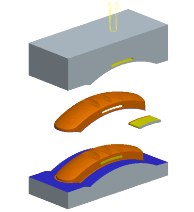
- Notice the different surface colors. The default colors indicate:
- Blue = steel to steel contact between tooling components for shutoff
- Yellow = steel to steel contact between slider surfaces and mold plates
- Select Done/Return.
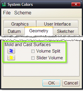
- Review the color options under:
View > Display Settings > System Colors... > Geometry tab
|

|
If these colors are changed, existing split surfaces will update upon regeneration. |
You have completed the Manufacturing Solutions Tutorial.