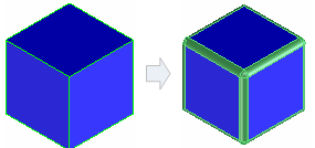
Creo Elements/Direct Modeling offers you powerful blend functions to replace sharp edges with curved faces (blends). These types of edges are also called fillets in other CAD systems.
Edges can be blended by specifying either a constant radius, which creates a blend with the same radius along the length of the edge, or a variable radius, which creates a blend with different radii at the beginning and end.
If you are working on a complex part, leave blending operations until your design is in the final stages. The processing time for the display and modification of complex surfaces like blends is longer than the time needed for less complex surfaces.
To create or insert a blend,
1. Click Modeling and then, in the Engineering group, click the arrow next to Blend.
2. Click Constant, Variable 2, or Variable n. The Create Blend dialog box opens.
3. Select a Type: Constant, Var 2 Radius, or Var N Radius.
4. Click Chain Selection if you want to select all tangentially connected edges with a single click. The sequence of edges stops when two edges are not tangentially connected, such as when the edge intersects with a corner.
5. Edit Definition: The Edit Definition check box is selected by default.
◦ You can change the definition of the current blend. For example, you can change the type of the blend. You can also select other edges to create the blends of the selected type.
◦ Clear the Edit Definition check box to complete the current blend and start creating a new blend on another edge without exiting the Create Blend command. You can create a blend of any type on the other edge.
6. Click Edges and select the edge to blend in the viewport. Press Shift to select multiple edges.
• Select an edge in the viewport and click or on the Command Mini Toolbar (CMT) to create a constant radius blend or variable radius blend respectively.
• While creating a blend, drag the CoPilot arrows, press SPACEBAR, and select Radius or Intersect on the Option Mini Toolbar (OMT). The options available on the OMT depend on the selected element.
7. Enter a value for Radius and press ENTER. If you create a Var 2 Radius blend, set the Start Radius and End Radius. Set additional points in a Var N Radius blend by clicking on the desired points along the edge. You can drag the guide arrows in the viewport to change radii.
Click Clear active selection to deselect the selected blends.
◦ Intersect: The blend doesn't propagate over other edges.
◦ OnTanFaces: The blend faces will propagate over edges of tangentially connected faces.
◦ OnSharpEdge: The blend faces will propagate along sharp edges and over edges of tangentially connected faces.
◦ OnAnyEdge: The blend faces will propagate along tangent and sharp edges of connected faces.
9. Select Curvature Continuous to create a smooth transition between blend boundaries. Use this option when defining a visible contour of a shape, especially when working with large radii.
10. Set the Affected Control options. These options allow you to decide which (if any) existing blends are affected by new blends.
◦ Auto: Creo Elements/Direct Modeling automatically selects the blends.
◦ Manual: Manually select the blends to be affected.
◦ Min: Select the minimum number of affected blends.
◦ Max: Select all affected blends.
11. Other options:
◦ Feedback: Shows a wire frame preview of the blend.
◦ Labels: Add radius labels to each blend to show where the entered values are applied. The Labels option in the Create Blend dialog box adds labels to each blend with the radius. To change the default setting for labels, see
Change Modeling settings.
◦ Dragging: Displays the CoPilot handles. Drag the handles to make the radius larger or smaller.
◦ Chk & Fix: Check and attempt to fix self-intersections, knife edges, and void shells. If a part fails the check and fix, it is not modified and remains in its original state.
• You can click either Realistic or Quick to see either realistic feedback or quick feedback when you blend an edge in the viewport. See
Realistic feedback.
• You can press SPACEBAR or the assigned key to open the Option Mini Toolbar (OMT) and select (Next blend definition) on the OMT to complete the current blend and start creating a new blend (any type on any edge) without exiting the Create Blend command.
• Click Preview to preview the model with blends.
12. Click to complete the operation.
Limitations
• You can't blend a closed circular edge with a variable radius.
• You can only blend up to six edges meeting at a single vertex.
• If a blend intersects with a boss or pocket, you must use the Chk & Fix option or the part will be corrupt.
• Blends created with the OnSharpEdge and OnAnyEdge options will fail if the touched edge has a common vertex with the blend.
 Blend.
 Variable 2, or
  Variable n. The Create Blend dialog box opens.
 (Next blend definition) on the OMT to complete the current blend and start creating a new blend (any type on any edge) without exiting the Create Blend command.
 to complete the operation.