
Contact with Friction
Users have the ability to add friction to individual contact regions. Once contact is enabled, users may also define "slippage measures." Measures will let users know if the normal force with the friction coefficient specified is enough to keep the parts from moving. Friction can be used to keep contact models from being under constrained in static analyses.
|
|
The functionality covered in this tutorial is included with Pro/ENGINEER Mechanica. |
1. Open ![]() FRICTION_ASM.ASM.
FRICTION_ASM.ASM.
|
|
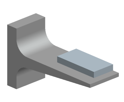
This model is made up of two parts that are both made of aluminum. You are going to run this simulation with friction and without friction. Contact definition is part of Pro/Engineer Mechanica licenses. |
2. Applications > Mechanica > Continue.
|
|
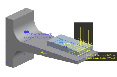
The material assignments, loads, constraints, measures and contact regions have already been defined for you. |
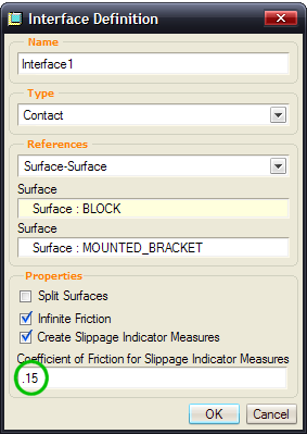
3. Review the contact interface.
- In the model tree, click Connections > Interfaces
- Right click on
 Interface1
- Select Edit Definition
- Note that the coefficient of Friction is .15
- Close the dialog box
|
|
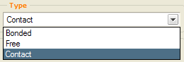
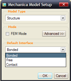
This dialog box is used to create all free, bonded and contact interfaces.
OPTIONAL: In Pro/ENGINEER Wildfire 4.0, you can set a default state of coincident surfaces or components in an assembly model. You can choose to merge them, leave them free, or create contacts between them. If you'd like to explore this, go to Edit > Mechanica Model Type and select the Default Interface selection. Leave it at Bonded for this exercise. |
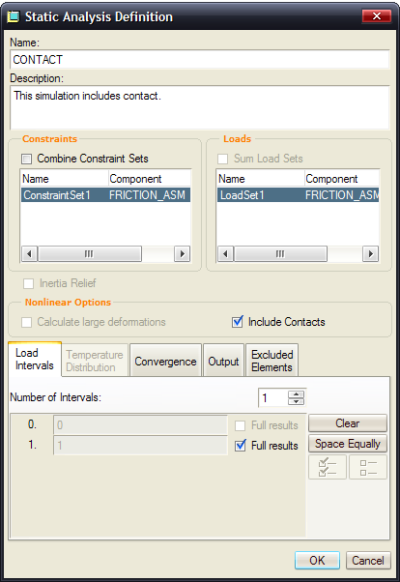
4. Use the Run a Design Study ![]() icon.
icon.
- Click File > New Static
- Name the study - CONTACT
- Complete the dialog box as follows
5. Click the Start Run ![]() icon.
icon.
- Click YES to Do you want to run Interactive Diagnostics
- Click Display Study Status
 to check progress of study
|
|
The study runs very quick |
- Close the Diagnostics dialog box that has popped up
- With the CONTACT analysis highlighted, click the Results
 icon
icon
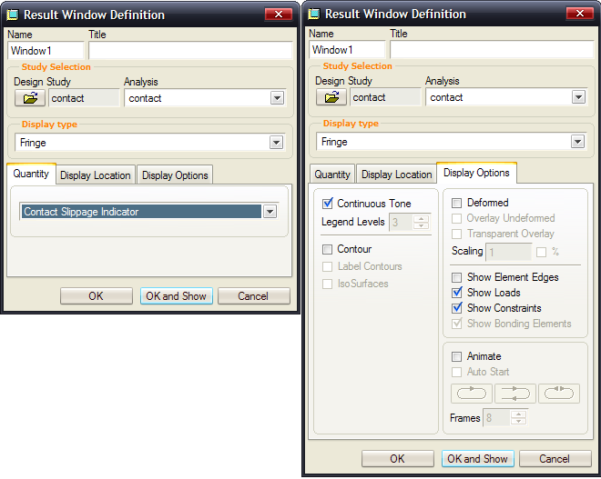
6. Fill out the Result Window Definition dialog box as follows. Click OK and Show when finished.
(use the 'Click to view larger picture button' below to expand image)
7. Your Results look like this:
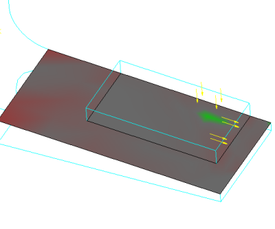
8. Notice the green area. No slippage occurred here because of the pressure load in that area.
|
|
The Contact Slippage Indicator is an automatic measure that is created when friction is defined with contact. |
| Color | Value of Slippage Indicator Measure | Slippage |
|---|---|---|
|
Red |
S > 0 |
Yes |
|
Green |
S < 0 |
No |
|
Gray |
S = 0 |
- |
9. File > Exit Results > NO and close out of dialog boxes.
10. Window > Close ![]() .
.
You have completed this Exercise, continue to Next Page.