![]()
Simulation Products Mission:
“Provide the spectrum of Pro/ENGINEER users, from designers through analysts, a fully integrated suite of world class applications for the evaluation and improvement of all aspects of product design performance.”
|
|
Simulation Products Mission: |
Highlights of other enhancements in the area of Simulation:
* Denotes functionality in Pro/ENGINEER Advanced Mechanica. The remaining functionality in this tutorial is available in Pro/ENGINEER Mechanica.
|
|
Pro/ENGINEER Mechanica is now fully unified as a module of Pro/ENGINEER during install using PTC.Setup. This streamlines the process, and eliminates the risk of a version mismatch. |
Hyperelastic materials, such as rubber, are nonlinear materials that exhibit instantaneous elastic response to large strains. Mechanica uses an industry leading material definition UI to bring this complex nonlinear solution capability to non-specialist users.
Mechanica supports several different mathematical models of hyperelastic material. Material properties can be defined by experimental data or using popular material laws such as Arruda-Boyce, Mooney-Rivlin, Neo-Hookean, etc.
|
|
This functionality covered in this tutorial requires Pro/ENGINEER Advanced Mechanica. |
The Working Directory for all the Simulation tutorials is SIMULATION.
|
|
This model is made up of two steel plates that sandwich some elastic material. We are going to review the material properties and review the results of this analysis. |
|
|
This model already has material properties, loading conditions and constraints. You will first review the material properties for the parts in this assembly. |
|
|
Currently the material is being defined by a text file called Test1 and you can see the two columns of data on the left side. The UI is set to select the best fit automatically and has selected the Yeoh material law. |
|
|
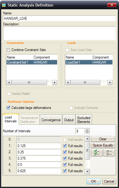
Note that the check box for Calculate large deformations is checked. This is necessary for the nonlinear material definitions to be in effect. |
|
|
Erasing the barrier separating design and analysis . . . . Unparalleled CAD/CAE Integration! |
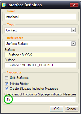
Users have the ability to add friction to individual contact regions. Once contact is enabled, users may also define "slippage measures." Measures will let users know if the normal force with the friction coefficient specified is enough to keep the parts from moving. Friction can be used to keep contact models from being under constrained in static analyses.
|
|
The functionality covered in this tutorial is included with Pro/ENGINEER Mechanica. |
1. Open ![]() FRICTION_ASM.ASM.
FRICTION_ASM.ASM.
|
|
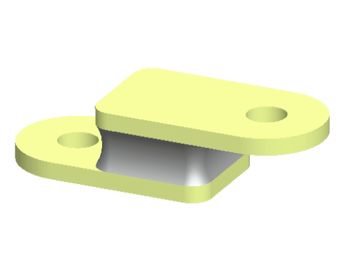
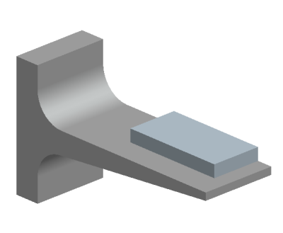
This model is made up of two parts that are both made of aluminum. You are going to run this simulation with friction and without friction. Contact definition is part of Pro/Engineer Mechanica licenses. |
2. Applications > Mechanica > Continue.
|
|
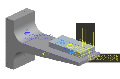
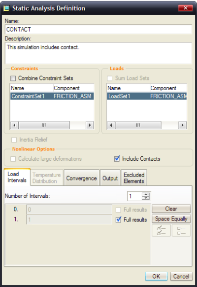
The material assignments, loads, constraints, measures and contact regions have already been defined for you. |
3. Review the contact interface.
|
|
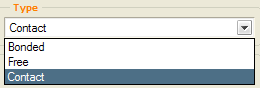
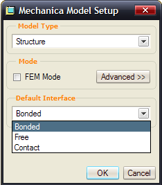
This dialog box is used to create all free, bonded and contact interfaces.
OPTIONAL: In Pro/ENGINEER Wildfire 4.0, you can set a default state of coincident surfaces or components in an assembly model. You can choose to merge them, leave them free, or create contacts between them. If you'd like to explore this, go to Edit > Mechanica Model Type and select the Default Interface selection. Leave it at Bonded for this exercise. |
4. Use the Run a Design Study ![]() icon.
icon.
5. Click the Start Run ![]() icon.
icon.
|
|
The study runs very quick |
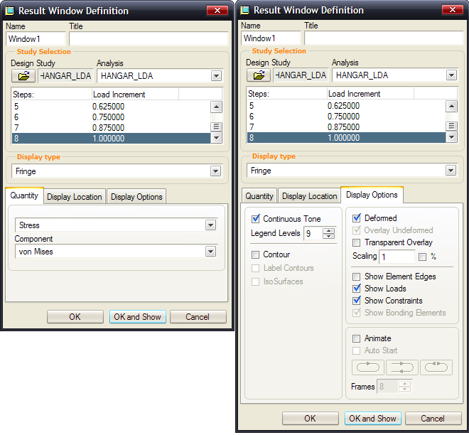
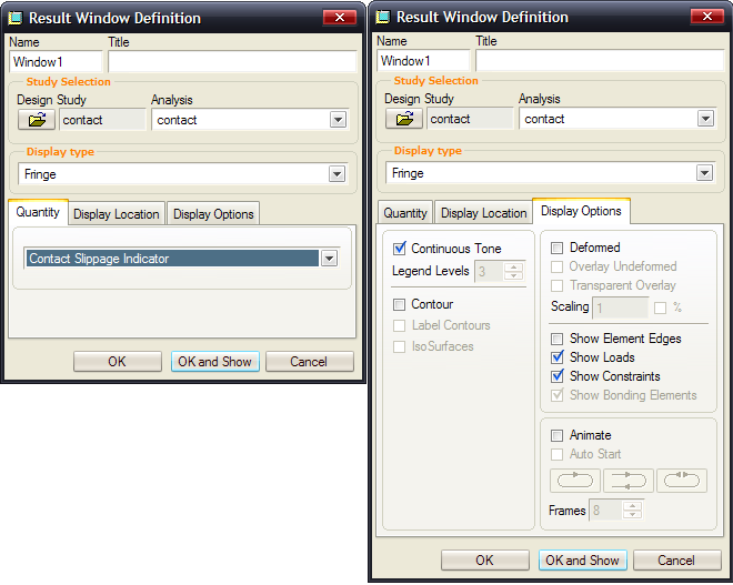
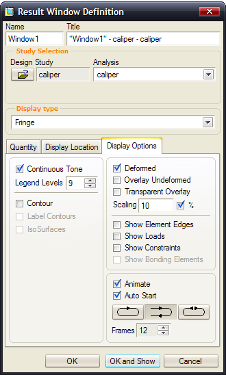
6. Fill out the Result Window Definition dialog box as follows. Click OK and Show when finished.
(use the 'Click to view larger picture button' below to expand image)
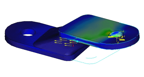
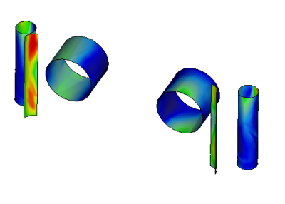
7. Your Results look like this:
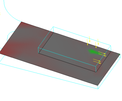
8. Notice the green area. No slippage occurred here because of the pressure load in that area.
|
|
The Contact Slippage Indicator is an automatic measure that is created when friction is defined with contact. |
| Color | Value of Slippage Indicator Measure | Slippage |
|---|---|---|
|
Red |
S > 0 |
Yes |
|
Green |
S < 0 |
No |
|
Gray |
S = 0 |
- |
9. File > Exit Results > NO and close out of dialog boxes.
10. Window > Close ![]() .
.
The intent of this tutorial is to highlight enhancements made to displaying results in Mechanica.
|
|
The functionality covered in this tutorial is included with Pro/ENGINEER Mechanica. |
1. Open ![]() 4913003.asm.
4913003.asm.
|
|
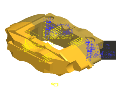
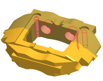
This assembly is made up of two halves of a brake caliper. Both of these parts are made up of aluminum alloy. |
2. Applications > Mechanica > Continue.
|
|
All of the materials, constraints and loading conditions have been applied and the analysis has already been run. |
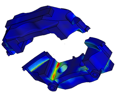
3. Create a result window.
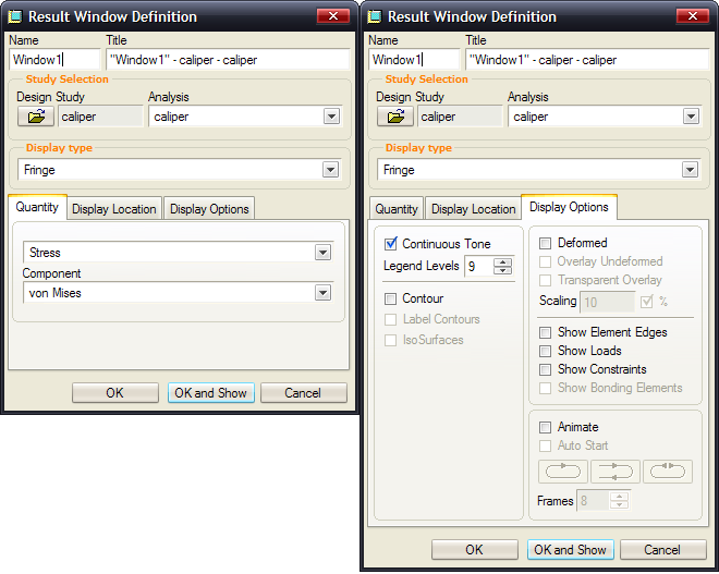
4. Change the Legend values on screen.
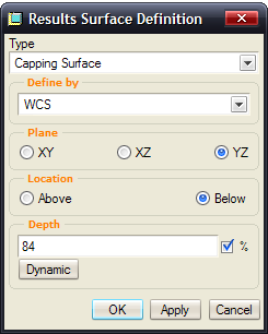
5. Use Dynamic query on a capping surface
|
|
Notice that the stress value changes with the mouse location. You can relocate the Query box by selecting it with your mouse and moving it. |
|
|
Making sophisticated analyses accessible to design engineers |
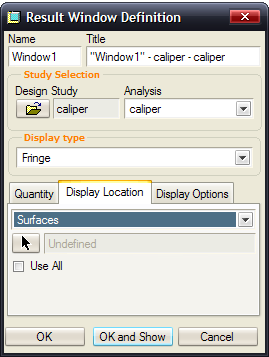
6. Change results to only show stress on selected surfaces.
|
|
This was possible in previous versions, but now you are able to select surfaces directly from the Pro/Engineer model instead of the Mechanica mesh model. |
7. Explode state during results.
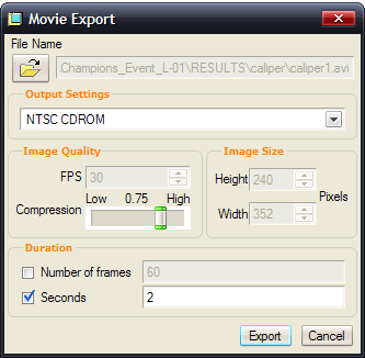
8. Create an AVI file.
9. File > Exit Results > NO and close out of dialog boxes
10. Window > Close ![]() .
.