Task 4. Dimension sketch of shaft and extrude
-
Click the Dimension
 icon and create the first dimension
a. left-click the vertical line on the left side (point 1)
b. left-click the dashed line in the middle of the lobe (point 2)
c. middle-click anywhere in-between the two lines (point 3) to place the dimension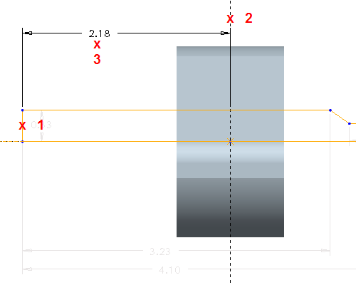
-
Create another dimension by left-clicking on points 1 and 2, and then middle-clicking on point 3 to place the dimension.
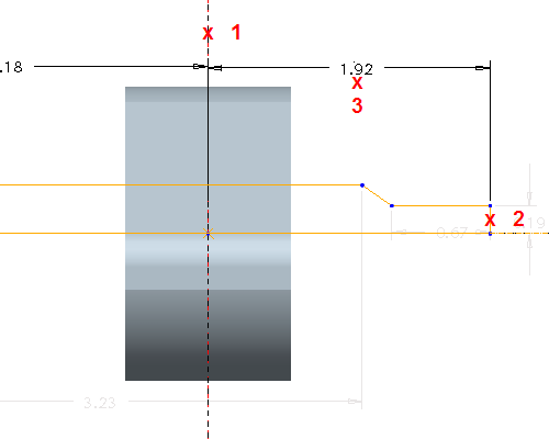
-
Create the final linear dimension by left-clicking point 1, and then middle-clicking point 2 to place the dimension.
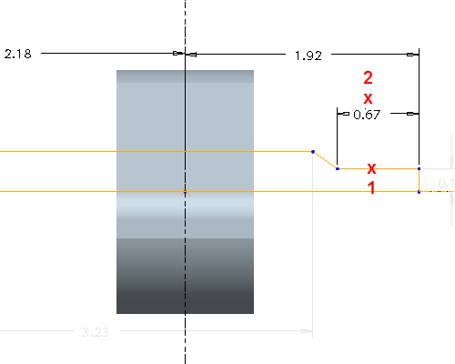
-
Create an angular dimension. Left-click points 1 and 2, then middle-click point 3 to place the dimension.

-
Create diameter dimension.
a. Left-click horizontal line entity (point 1)
b. Left-click centerline to revolve about (point 2)
c. Left-click horizontal line entity again (point 3)
d. Middle-click to place the dimension (point 4)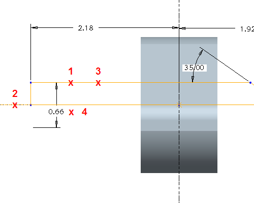

This dimensioning technique is very useful when creating revolved features because it shows the dimension as a diameter.
-
Create diameter dimension on the opposite side. Left-click point 1, followed by point 2, followed by point 3, then middle-click point 4.
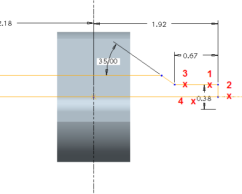
-
Click the Select Items
 tool. Double-click each dimension, and change them to where their corresponding values match the figure below.
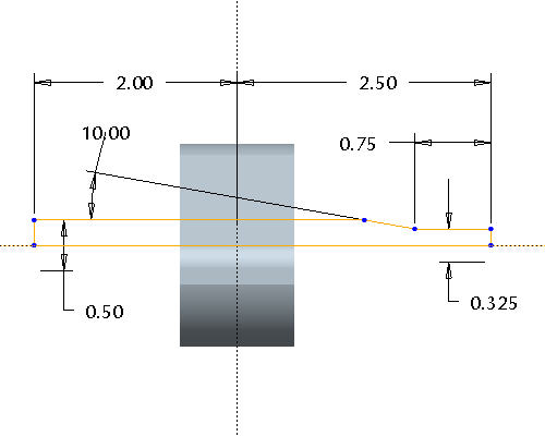
-
Click the Complete Sketch
 icon in the sketcher toolbar to complete the sketch.
 -
With the sketch still selected, click the Revolve
 tool on the feature toolbar.
 -
Click the Complete Feature
 icon in the dashboard.
 -
Press CTRL+D on your keyboard to see the default view of your model.

