Task 2. Constrain and dimension the lobe sketch and extrude
-
Click Constraints
 from the sketcher toolbar, then click Same Points
  tool from the Constraints dialog box.
 -
Click the center point of one of the fillets, followed by any point on the dashed horizontal line.
-
Click the Close button from the Constraints dialog.
-
Click the Dimension
 in the main toolbar to enable the display.
 -
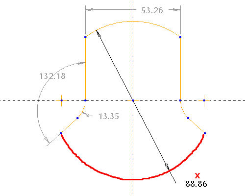
Double-click the arc highlighted in the following figure, and middle-click around the red x to place the diameter dimension. Ignore the dimensional value for now.


Sketcher will always make sure sketches are adequately constrained and dimensioned. Any dimensions the system automatically creates appear in light grey and are called "weak" because the system will delete them without user input if conflicting dimensions and/or constraints are created by the user. Any user-created dimensions appear dark and are called "strong", and will not be deleted without confirmation from the user.
-
With Dimension
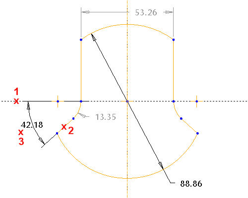
 still selected left-click where points 1 and 2 are shown, and middle-click at point 3 to create an angular dimension. Ignore the dimensional value for now.
-
Middle-click again to exit the dimensioning tool.
-
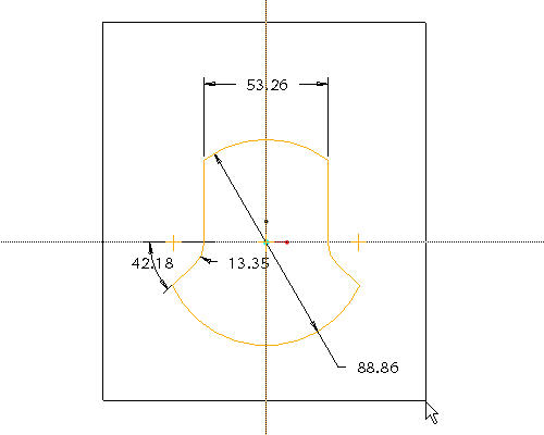
Click Select Items
 in the Sketcher toolbar and draw a selection box around all the dimensions. Start the selection box by left clicking at the top of the sketch and dragging the cursor and releasing the left mouse button. All the dimensions should highlight.
-
Click Modify Values
 and select the check box Lock Scale. Then select the diameter dimension (88.96) and type 2.
 -
Click Regenerate Section
 to complete the modification.
 -
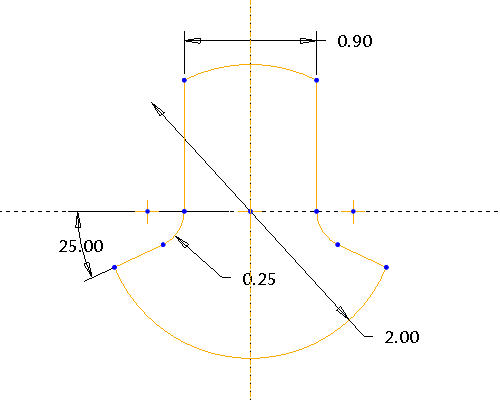
Double-click each dimension to edit their values, and edit them so that they are the same as the following figure.

-
Select the Complete Sketch
 icon in the sketcher toolbar to exit the sketch.
 -
Press CTRL+D to see model in default orientation.
-
Click the Extrude
 icon with the sketch selected.
 -
Select Both Sides
 from the pull down in the dashboard as the depth direction, and enter 1.125 as the depth.
-
Select the Complete Feature
 icon in the dashboard.

In order to return back to the definition a feature, right click on the feature in the model tree or on screen and Edit Definition. This is useful if you have made a mistake or want to change the feature shape or other options.
