Task 1. Sketch entities to develop the shape of the lobe
-
Start Pro/ENGINEER Wildfire 4.0 Schools Edition if necessary.
-
If Pro/ENGINEER is already running, close all windows and remove all objects from session using File > Erase > Not Displayed...
-
File > Set Working Directory... , and browse to HANDS-ON_WF4\03-SKETCHER
-
Click the Create New Object
 icon on the main toolbar at the top left of the screen. The New object dialog opens.
 -
Accept the default settings in this dialog and click OK.

Default templates are used when a new part or assembly is created. The default templates are an initial design model that contains default features, layers, views, parameters and units.
-
Click the Sketch Tool
 icon on the right toolbar to create a sketch.
 -
Click the datum plane named FRONT as the sketch plane, then click Sketch from the Sketch dialog in the upper right corner of the screen. This brings you into the sketching environment.
-
Click the Datum Planes
 , Datum Axes
  , Datum Points
  , and Coordinate Systems
  icons on the main toolbar.

These buttons toggle datum planes, axes, points and coordinate systems on and off so that your graphics window doesn't become too cluttered.
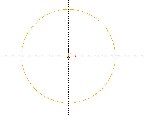
- Click on the Circle
 tool. Click where the vertical and horizontal dashed lines meet to place the center of the circle, then move the mouse away from the center point and left-click to finish creating the circle.
-
Hold down the right-mouse button, and a context-sensitive menu will appear
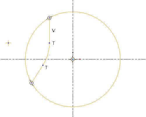
Select Line, and click location 1 as shown in the figure below to start the line. Note a rubber band line appears attached to the cursor.
Click location 2 in the figure to end the line. Pro/ENGINEER creates a line between the two points and starts another rubber band line.
Click location 3 in the figure to create the second line. The two lines are shown in the figure below.
-
Middle-click to end the line creation.

Click Sketch Orientation
 if you accidentally rotate the Sketcher view.
 -
Click the Sketch Fillet
 tool, and click the two lines just created.
-
In the upper right portion of the screen, click on the arrow next to the Line
 icon. A flyout toolbar will appear.
 -
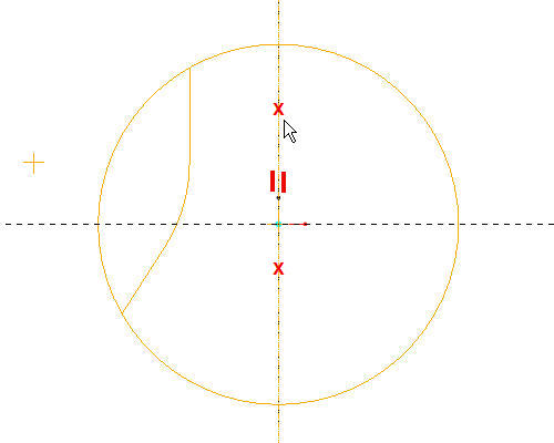
Click on the Centerline
 icon and then create a centerline by left-clicking two points on the vertical dashed line, as shown in the figure below.
-
Middle click to end the centerline creation.
-
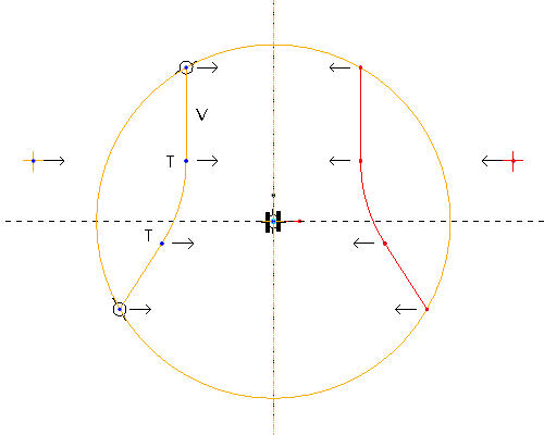
Hold the CTRL key down, and select the two lines and arc.
-
Select the Mirror
 tool in the sketch toolbar, and then click on the vertical centerline on the sketch.
-
Click on the Dynamic Trim
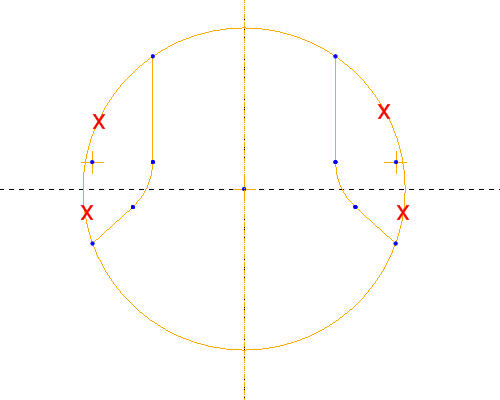
 tool, and hold the LMB down to drag select over the four locations indicated below.
-
Click the Select Items
 icon on the sketcher toolbar (or press MMB) when completed.
