Task 3. Create Rounds
- Start the Round Tool
 from the right toolbar.
|
|
Rounds add or remove material by creating smooth transitions between existing geometry. Pro/ENGINEER awaits the selection of edges and/or surfaces to determine round locations. |
- Press and hold CTRL on the keyboard and select the four vertical edges on the model as shown below.
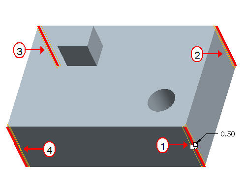
- Double click the radius dimension and modify its value to 2.
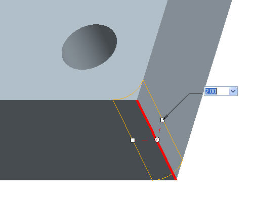
- Click Complete Feature
 from the dashboard in the lower right hand corner of the screen.
- Start the Round Tool
 from the right toolbar again.
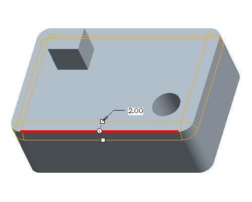
- Select the top edge as shown below.
|
|
The surfaces bordering the edge reference form the rolling tangent attachment for the round. The round propagates across tangent neighbor edges unit it encounters a break tangency. |
-
Click Complete Feature
 from the dashboard in the lower right hand corner of the screen.
 -
Start the Round Tool
 from the right toolbar again.
 -
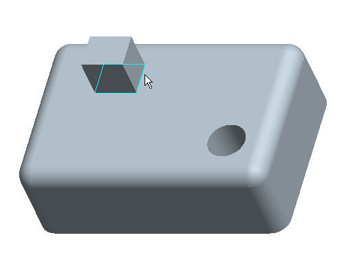
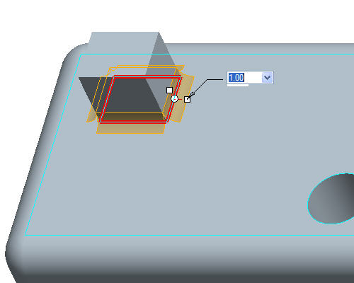
Cursor over the edge at the base of the 2nd extrude feature and while it is highlighted, click the right click once. See the location of the cursor shown below.
-
While the loops of edges around the base of that feature are highlighted, click once with the left click to select them, as shown below.
-
Double click the radius value and modify it to 1.
|
|
Aside from single or tangent edges, the user can select an "Intent chain" which enables the round to select the references by the feature rather than by specific entities. |
-
Click Complete Feature
 from the dashboard in the lower right hand corner of the screen.
