Working With Autodesk Inventor Tube And Pipe Module In Windchill
Windchill 11.0 M010 onward, the Tube and Pipe module of Autodesk Inventor is supported in Windchill Workgroup Manager.
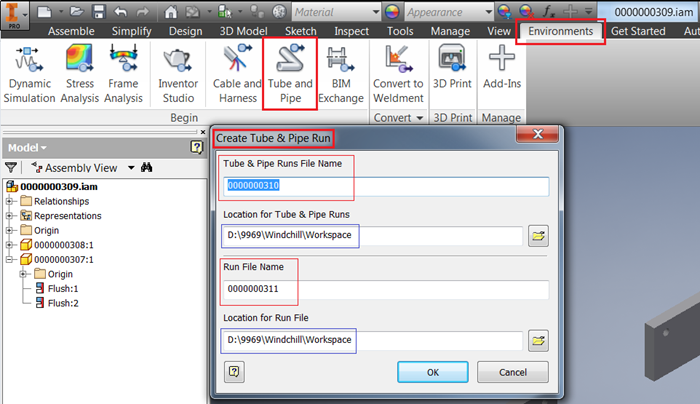
1. In an Autodesk Inventor assembly, click > .
The Create Tube & Pipe Run window opens with the Tube & Pipe Runs File Name and Run File Name fields populated and location for both set to default Windchill workspace.
If the Windchill Workgroup Manager is connected to Autodesk Inventor, the Tube & Pipe Runs File Name and Run File Name are named as per the following rules:
◦ If Windchill CAD Document Auto-numbering is ‘ON’, their names follow the auto-numbering scheme i.e. auto-generated number.
◦ If the Windchill CAD Document Auto-numbering is ‘OFF’ or if the preference Synchronize File Name and Number is ‘No’, their names follow the Autodesk Inventor naming convention:
▪ Tube and Pipe runs filenames are<Mainassemblyname>.Tube and Pipe Runs.iam.
▪ Run file name is <Mainassemblyname>.Run01.iam.
◦ If you click the Cancel button or close the Create Tube & Pipe Run window, and then relaunch the Create Tube & Pipe Run window, new names are generated.
◦ If you click

on the
Create Tube & Pipe Run window, the
Autodesk Inventor ‘Save As’ window appears and auto-number gets iterated.
| Do not change the save location for the Tube & Pipe Runs File Name and Run File Name. |
| Standalone Autodesk Inventor creates a particular folder structure runtime while creating Tube and Pipe data. When Windchill Workgroup Manager is connected to Autodesk Inventor, all the components are created in Windchill workspace. |
2. Click OK on Create Tube & Pipe Run window to close it.
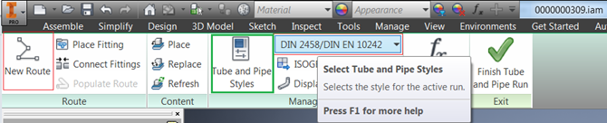
3. You can select a Tube and Pipe style from the styles available in Autodesk Inventor as shown in the following image. You can also configure your own style using the Tube and Pipe styles window, set the newly created style as active, and use it.
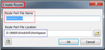
4. After selecting the Tube and Pipe Style click the New Route button to open the Create Route window.
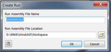
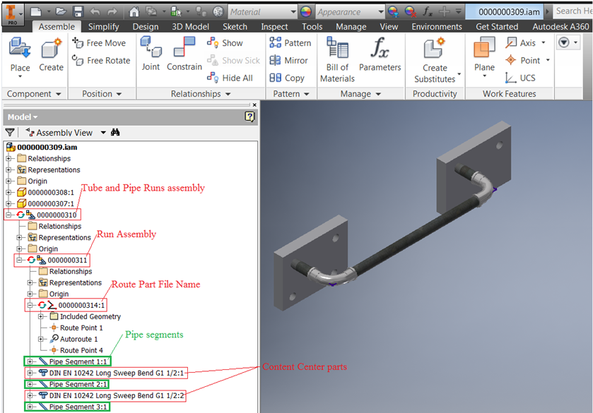
On the Create Route window, the Route Part File Name follows the same rule as Tube & Pipe Runs File Name and Run File Name and the path is set to default Windchill workspace. On the Create Run window, the Run Assembly File Name also follows the same naming rules when you create additional run in existing Tube and Pipe assembly.
Figure 1. Create Route window
Figure 2. Create Run dialog during creation of additional Run
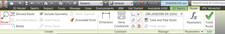
Creating a route and run enables the Route button as shown below.
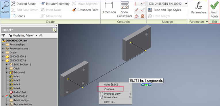
5. Click Route and select the points or path for its creation. In the following image, the threaded holes in the part 0000000307.ipt and 0000000308.ipt are selected as shown. After selecting the path, right-click in the graphics window and select Continue as shown below.
The path changes its color to violet.
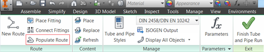
6. Click the Finish Route button. This enables the Populate Route button.
7. Click the
Populate Route button to generate the conduits or pipe segments and the content center parts. The behavior for the content center parts is different depending on the setting of the preference
Define Library used by application. For more information, see
Using Autodesk Inventor Content Center with Windchill.
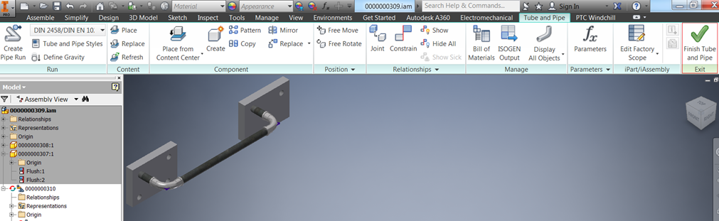
The assembly is displayed as shown below after the tube and pipe components are populated.
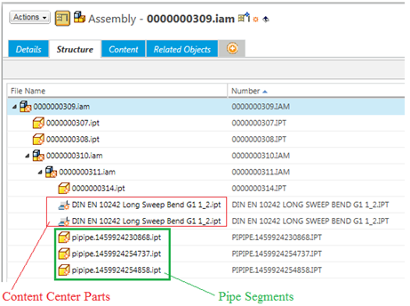
The Autodesk Inventor Assembly feature tree and the Assembly structure in Windchill after save of the main assembly is shown below.
Figure 3. Assembly Structure
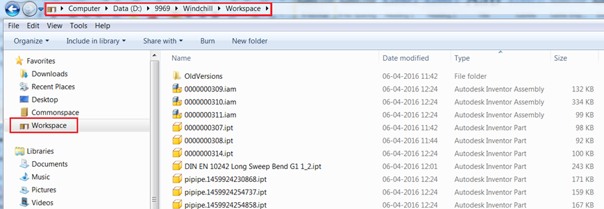
After save of the main assembly, the Windows Explorer shows all the files in the Workspace location. See the following image.
Naming Behavior for Tube and Pipe Components
Conduits or Pipe segments and Content Center parts are named as per the Autodesk Inventor naming convention; for example, pipipe.1459924230868.ipt and DIN EN 10242 Long Sweep Bend G1 1_2.ipt respectively.
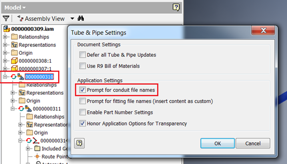
To open Tube & Pipe Settings window, right-click the Tube and Pipe runs assembly and click Tube & Pipe Settings.
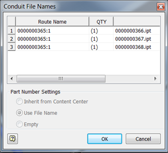
On the Tube & Pipe Settings window, if you click the Prompt for conduit file names check box, then the conduits/pipe segments are also named as per the Windchill CAD Document auto-numbering scheme.
After this setting is done, when you create run and populate the route using Populate Route command, the Conduit File Names window is displayed where the conduits names are auto-numbered.
Find Number and Line Number Propagation
Find Number and Line number propagation happens properly if you go to the BOM of each Run assembly as well as Tube and Pipe Runs assembly and activate the Structure tab. The Test tube and Pipe Runs assembly as well as the Route parts are flagged as Phantom in
Autodesk Inventor and as such do not appear in the ‘Bill of Materials’ and ‘Structured tab’. For more information about Find number Line number, see
Using Autodesk Inventor BOM with Windchill.
For import behavior (best practices), see
Import to Workspace.
Limitations
• For an Autodesk Inventor Tube and Pipe assembly that is created using ‘Save As’ action from Windchill, the Autodesk Inventor assembly feature tree:
◦ Does not update the names of the tube and pipe data (except for Route file name) and,
◦ Displays older names (names appearing in the parent assembly from which Save As has been done).
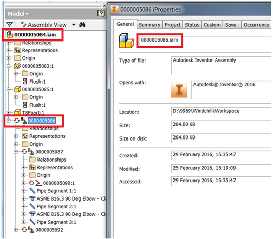
These include the Tube and Pipe Runs assembly, Run assemblies, Content Center files, and Conduits/File segments as shown in the following image:
Figure 4. Before Save As
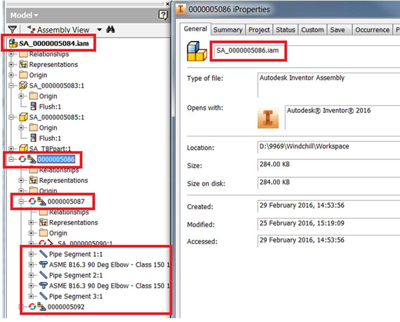
Figure 5. After Save As
| Except for the Route SA_0000005090, all tube and pipe components display their old names in the feature tree. However, the iProperties window displays the updated names after Save As. |
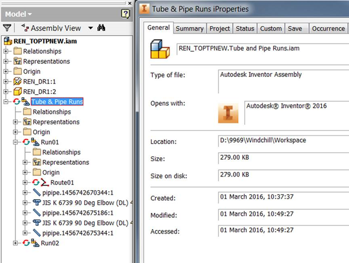
• If you rename an assembly in Windchill Workgroup Manager, Tube and Pipe components do not show the updated name in the feature tree. However, if you click > in Autodesk Inventor, the Tube & Pipe Runs iProperties window displays the updated name as shown in the following image.
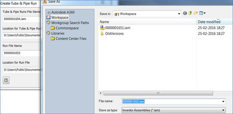
• While creating a Tube and Pipe assembly, in the
Create Tube & Pipe Run window, if you click
, the
Save As window displays an incremented number as shown in the following image.
• While re-importing a Tube and Pipe assembly that is already checked-in to Windchill, import from Specify Options page with Reuse option selected for the standard parts (Library or Content Center parts). If Import to Workspace is done with Add as modified, Check out, and Revise and Checkout options for the standard parts, the following message is displayed after opening and saving the parent assembly.
“Documents being saved have a reference of documents outside the Workspace”
• During creation of Tube and Pipe data in Autodesk Inventor 2017, if you change the Run File name, the Run File location automatically changes. The following error is displayed:
“Could not create a new folder”.
The error occurs because Windchill File System does not allow creation of folder at runtime.