Internal block diagram (SysML diagram)

The Internal Block Diagram in SysML captures the internal structure of a block in terms of properties and connectors between properties. A block can include properties to specify its values, parts, and references to other blocks. Ports are a special class of property used to specify allowable types of interactions between Blocks.
Create an Internal Block Diagram from a Block: right-click the Block, and select > > .
When you create an Internal Block Diagram, Modeler adds a frame to the diagram and links that frame to the Internal Block Diagram.
You can add the owning Block to an Internal Block Diagram: right-click the diagram background, and select > , and then click Owner - Modeler sizes the Block to fit within the frame or to contain the items shown on the diagram.
Items outside of the scope of the owning Block will be shown within the owning Block on the diagram - if you move such an item within the owning block, that item will be rescoped to the owning Block. |
Create new items and relationships on an Internal Block Diagram, such as Block Properties, Flow Ports and Connectors, through the diagram's tab buttons.
You can also create Block Properties, ports and Item Flows by dragging the item that is to be the type or conveyed classifier from an appropriate pane to the diagram:
• Drag a Block, Interface Block or Value Type to the diagram background, within a Block or within a Block Property to create a Block Property that uses the dragged item as its type.
• Drag a Block, Interface Block, Flow Specification or Value Type to the edge of a Block or Block Property to create a Flow Port, Full Port or Proxy Port that uses the dragged item as its type.
• Drag a Class or Interface to the edge of a Block or Block Property to create a Standard Port that uses the dragged Class or Interface as its type.
• Drag a Block, Interface Block, Flow Specification, Signal or Value Type to an Actor Connector, Connector or Binding Connector to create an Item Flow that uses the dragged item as its conveyed classifier.
Add existing items and relationships to an Internal Block Diagram through the Populate commands that are available when you right-click the diagram background or an item on the diagram. Alternatively, click the appropriate button, right-click within the containing item, and then click the command for the existing item you want to add.
You can determine the default presentation of SysML items when they are added to an Internal Block Diagram through the Default View Options: right-click the diagram background (not within the Block if shown), and then click to View Options. After adding an item to an Internal Block Diagram, you can change its presentation through the standard Modeler View Options: right-click the item, and then click View Options.
You cannot move an Internal Block Diagram to a different Package directly, but if you move a Block that owns an Internal Block Diagram to a different Package, the Internal Block Diagram is moved with the owning Block.
When working with Internal Block Diagrams, do not roll up features using the Roll Up, Roll Up Features and Roll Up Contextual Features commands. |
All Internal Block Diagrams are shown in the  Blocks pane - expand the InternalBlockDiagram folder.
Blocks pane - expand the InternalBlockDiagram folder.The Internal Block Diagram is a UML Composite Structure Diagram that is stereotyped by the «Internal Block Diagram» stereotype from the SysML profile.
For information about adding Requirements to an Internal Block Diagram, see the SysML > Requirements section of this Help.
An Internal Block Diagram shows the following items.
Actor (UML item)

Create new Actors through the  Actor button on the diagram's tab: click the Actor button, and then click in free space.
Actor button on the diagram's tab: click the Actor button, and then click in free space.Add an existing Actor to an Internal Block Diagram by dragging the Actor from an appropriate pane to the Internal Block Diagram. Alternatively, click the Actor button, right-click in free space, and then select an Actor from the diagram's Package to add.
Actor button, right-click in free space, and then select an Actor from the diagram's Package to add.To populate an Internal Block Diagram with Actors that are in the same Package as the diagram: on the diagram, right-click in free space, point to Populate, point to Nodes, and then click Actors. To add an Actor from outside of the diagram's Package, drag the Actor from an appropriate pane to the diagram.
To populate the Associations that relate to an Actor, right-click the Actor, point to Populate, point to Links, and then click Actor Connectors.
The view options of an Actor are set through the Actor entry on the View Options dialog.
Actor Connector

You can create Actor Connectors between an Actor and a Block Property, Flow Port, Full Port, Proxy Port or Standard Port.
Create new Actor Connector through the  Shallow Actor Connector or Shallow Uni-directional Actor Connector button or on the diagram's tab: Shallow Actor Connector or
  Shallow Uni-directional Actor Connector button, click the start item, and then click the end item. If a popup menu appears, click New or select an existing Actor Connector to add.
Shallow Actor Connector or Shallow Uni-directional Actor Connector button or on the diagram's tab: Shallow Actor Connector or Shallow Uni-directional Actor Connector button, click the start item, and then click the end item. If a popup menu appears, click New or select an existing Actor Connector to add.To populate Actor Connectors that are missing from the diagram: right-click in free space, point to Populate, point to Links, and then click Actor Connectors. To populate Actor Connectors that relate to an Actor, Block Property or port on the diagram, right-click the item, point to Populate, point to Links, and then click Actor Connectors.
The view options of an Actor Connector are set through the Association entry on the View Options dialog.
Binding Connector

Create a new Connector through the diagram's tab: click the  Shallow Binding Connector or Shallow Uni-Directional Binding Connector button, click the start Block Property, Full Port or Proxy Port, and then click the end Block Property, Full Port or Proxy Port.
Shallow Binding Connector or Shallow Uni-Directional Binding Connector button, click the start Block Property, Full Port or Proxy Port, and then click the end Block Property, Full Port or Proxy Port.Note that a Block Properties of type Part can be linked to only Block Properties of type Part. Block Properties of type Reference or Value can be linked to only Block Properties of type Reference or Value.
Add an existing Binding Connector to an Internal Block Diagram by clicking the Shallow Binding Connector or  Shallow Uni-Directional Binding Connector button on the diagram's tab, clicking the start item, clicking the end item, and then from the context menu clicking the Binding Connector you want to add.
Shallow Binding Connector or Shallow Uni-Directional Binding Connector button on the diagram's tab, clicking the start item, clicking the end item, and then from the context menu clicking the Binding Connector you want to add.To populate all Binding Connectors that are missing from the diagram: right-click in free space (outside the Block), point to Populate, point to Links, and then click Binding Connectors. To populate Binding Connectors that relate to a Block Property or port on the diagram, right-click the Block Property or port, point to Populate, point to Links, and then click Binding Connectors (Modeler adds any items required to show the Binding Connectors).
Note that a Binding Connector created between items in context cannot not be populated between those same items in a different context. In the following example, the Binding Connector shown in Block1 cannot be populated in Block4 because the Block Properties in Block4 are in a different context to those in Block1; however, if you use a Binding Connector button to add a new Binding Connector between BlockPropertyA and BlockPropertyB in the context of Block4, the context menu that is opened will allow you to add the Binding Connector in the new context, because the Binding Connector is defined in BlockProperty1's type (Block1).
Binding Connector button to add a new Binding Connector between BlockPropertyA and BlockPropertyB in the context of Block4, the context menu that is opened will allow you to add the Binding Connector in the new context, because the Binding Connector is defined in BlockProperty1's type (Block1).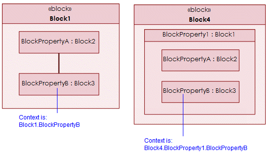
Also, a Complete Binding Connector allows the user to create ports at each end of the connector for the same operation.
The view options of a Binding Connector are set through the Association entry on the View Options dialog.
Block
When you create an Internal Block Diagram, Modeler does not add the parent Block to the diagram. To add the owning Block to the diagram: right-click the diagram background, point to Populate, point to Nodes, and then click Owner. In addition, if the owning Block is not shown and you add a Flow Port or Standard Port that is a child of the owning Block to the diagram, Modeler adds the owning Block to the diagram.
You can then create other diagram items, except Actors, within the Block - Modeler sizes the Block to fit within the frame or to contain the items shown on the diagram.
Items outside of the scope of the owning Block will be shown within the owning Block on the diagram - if you move such an item within the owning block, that item will be rescoped to the owning Block. |
The view options of a Block are set through the Class entry on the View Options dialog.
Block Property
Create new Block Properties of type Part through the  Block Property button on the diagram's tab: click the Block Property button and then click inside the Block or a Block Property on the diagram. You are prompted to select a type:
Block Property button on the diagram's tab: click the Block Property button and then click inside the Block or a Block Property on the diagram. You are prompted to select a type:If you select a Block or Interface Block to use as a type, Modeler creates a Block Property of type Part.
If you select a Value Type to use as a type, Modeler creates a Block Property of type Value.
Alternatively, you can create a Block Property by dragging the Block, Interface Block or Value Type that is to be the Block Property's type from an appropriate pane to the diagram background, the Block or a Block Property on the diagram.
Add an existing Block Property to the diagram through the Block Property button: click the Block Property button, right-click inside the containing Block or Block Property, and then from the dialog select the Block Property you want to add. Alternatively, you can drag the Block Property you want to add from an appropriate pane to the diagram.
Block Property button: click the Block Property button, right-click inside the containing Block or Block Property, and then from the dialog select the Block Property you want to add. Alternatively, you can drag the Block Property you want to add from an appropriate pane to the diagram.To populate missing Block Properties: right-click the diagram background, Block or Block Property, point to Populate, point to Nodes, and then click Block Properties.
When you create a Block Property within another Block Property on an Internal Block Diagram, it appears as though a Block Property owns a nested Block Property; however, the Block Property is created as a child of the nesting Block Property's type, and the Block Property you see on the diagram is a redefinition. For more information about redefinitions, click here
 .
.
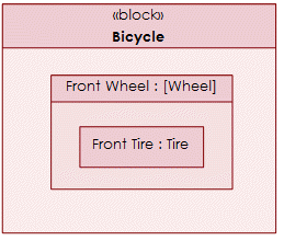
.If the Block Property contains a Block Property that has had its Default Value changed in context, the type of the containing Block Property is shown in brackets. In the following example, the Front Tire block property in context has a Default Value that is different from the Front Tire block property on the type, that is, the Wheel block.
To set or change a Block Property's type, right-click the Block Property, point to Set, and then click Type, Type (Redefinition Only) or Type (Top Level Definition).
To set the Multiplicity of a Block Property, right-click the Block Property, point to Set, and then click Multiplicity.
Connector

Create a new Connector through the diagram's tab: click the  Shallow Connector or
  Shallow Uni-Directional Connector button, click the start Block Property, Flow Port, Full Port or Proxy Port, and then click the end Block Property, Flow Port, Full Port or Proxy Port.
Shallow Connector or Shallow Uni-Directional Connector button, click the start Block Property, Flow Port, Full Port or Proxy Port, and then click the end Block Property, Flow Port, Full Port or Proxy Port.Add an existing Connector to an Internal Block Diagram by clicking the Shallow Connector or Shallow Uni-Directional Connector button on the diagram's tab, clicking the start item, clicking the end item, and then from the context menu clicking the Connector you want to add.
Shallow Connector or Shallow Uni-Directional Connector button on the diagram's tab, clicking the start item, clicking the end item, and then from the context menu clicking the Connector you want to add.To populate all Connectors that are missing from the diagram: right-click in free space (outside the Block), point to Populate, point to Links, and then click Connectors. To populate Connectors that relate to a Block Property or port on the diagram, right-click the Block Property or port, point to Populate, point to Links, and then click Connectors (Modeler adds any items required to show the Connectors).
Note that a Connector created between items in context, cannot not be populated between those same items in a different context. In the following example, the Connector shown in Block1 cannot be populated in Block4 because the Block Properties in Block4 are in a different context to those in Block1; however, if you use a  Connector button to add a new Connector between BlockPropertyA and BlockPropertyB in the context of Block4, the context menu that is opened will allow you to add the Connector in the new context, because the Connector is defined in BlockProperty1's type (Block1).
Connector button to add a new Connector between BlockPropertyA and BlockPropertyB in the context of Block4, the context menu that is opened will allow you to add the Connector in the new context, because the Connector is defined in BlockProperty1's type (Block1).Also, a Complete Connector allows the user to create ports at each end of the connector for the same operation.
The view options of a Connector are set through the Association entry on the View Options dialog.
Dependency (UML item)
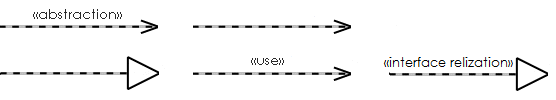
Create new Dependencies through the  Abstraction,
  Dependency,
 Realization and
  Usage buttons on the diagram's tab: click the appropriate button, click the client item, and then click the provider item.
Abstraction, Dependency, Realization and Usage buttons on the diagram's tab: click the appropriate button, click the client item, and then click the provider item.Add an existing Dependency to an Internal Block Diagram by clicking the Dependency button on the diagram's tab, clicking the start item, clicking the end item, and then from the context menu clicking the Dependency you want to add.
Dependency button on the diagram's tab, clicking the start item, clicking the end item, and then from the context menu clicking the Dependency you want to add.To populate Dependencies that are missing from the diagram: right-click in free space (outside the Block), point to Populate, and then click Dependencies. To populate only those Dependencies that relate to an item on the diagram, right-click the item, point to Populate, point to Links, and then click Dependencies.
The view options of a Dependency are set through the Dependency entry on the View Options dialog.
Flow Port
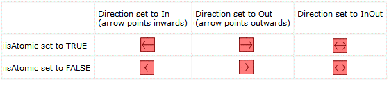
A Flow Port's notation depends on its direction and whether it is atomic or not (a Flow Port is atomic when its type is a Flow Specification).
Create new Flow Ports through the  Flow Port button on the diagram's tab: click the Flow Port button, and then click the Block (or diagram background if Block is not shown), Block Property or port that is to contain the Flow Port. Alternatively, you can create a Flow Port on an Internal Block Diagram by dragging the item that is to be the Flow Port's type (a Block, Interface Block, Flow Specification, Signal or Value Type) from an appropriate pane to the required Block or Block Property.
Flow Port button on the diagram's tab: click the Flow Port button, and then click the Block (or diagram background if Block is not shown), Block Property or port that is to contain the Flow Port. Alternatively, you can create a Flow Port on an Internal Block Diagram by dragging the item that is to be the Flow Port's type (a Block, Interface Block, Flow Specification, Signal or Value Type) from an appropriate pane to the required Block or Block Property.Note that if you create a Flow Port on a Block Property, the Flow Port is created as a child of the Block Property's type. The Flow Port that appears on the diagram is a virtual redefinition of the Flow Port on the type. For more information about redefinitions of Flow Ports, click here
When you create a Flow Port, you select its direction. To change a Flow Port's direction: right-click the Flow Port, point to Set, and then click Direction. If the Flow Port's type is a Flow Specification, the Direction must be inout. Note that when you change the direction of a Flow Port, the change is made to the Flow Port and all its redefinitions.
When you create a Flow Port, it is not conjugated by default. To change a Flow Port's conjugation: right-click the Flow Port, point to Set, and then click Is Conjugated. A Flow Port can be conjugated only when its type is a Flow Specification. Note that when you change the conjugation of a Flow Port, the change is made to the Flow Port and all its redefinitions.
To set or change a Flow Port's type, right-click the Flow Port, point to Set, and then click Type, Type (Redefinition Only) or Type (Top Level Definition). A Flow Port in context can have a different type to the Flow Port it redefines.
To populate missing Flow Ports: right-click the owning Block or Block Property, point to Populate, point to Nodes, and then click Flow Ports.
The view options of a Flow Port are set through the Port entry on the View Options dialog.
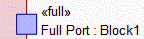
Full Port
Create new Full Ports through the  Full Port button on the diagram's tab: click the Full Port button, and then click the required item:
Full Port button on the diagram's tab: click the Full Port button, and then click the required item:The owning Block (or diagram background if Block is not shown)
A Block Property whose type is a Block or Interface Block.
A port whose type is a Block or Interface Block.
Note that if you create a Full Port on a Block Property or port, the Full Port is created as a child of the Block Property's or port's type. The Full Port that appears on the diagram is a virtual redefinition of the Full Port on the type. For more information about redefinitions of Full Ports, click here
To populate missing Full Ports: right-click the owning Block, Block Property or port, point to Populate, point to Nodes, and then click Full Ports.
The view options of a Full Port are set through the Port entry on the View Options dialog.
Interface (UML item)
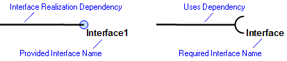
Create new interfaces through the  Provided Interface and
  Required Interface buttons on the diagram's tab: click the appropriate button, click the Standard Port for which the Interface is provided or required, and then double right-click in free space.
Provided Interface and Required Interface buttons on the diagram's tab: click the appropriate button, click the Standard Port for which the Interface is provided or required, and then double right-click in free space.Item Flow
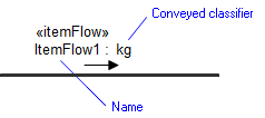
Create new Item Flows through the  Item Flow button on the diagram's tab: click the Item Flow button, and then click the Actor Connector, Connector or Binding Connector that realizes the Item Flow. Alternatively, you can create an Item Flow on an Internal Block Diagram by dragging the Block, Interface Block, Signal or Value Type that is to be the Item Flow's conveyed classifier from an appropriate pane to the Actor Connector, Connector or Binding Connector on the diagram.
Item Flow button on the diagram's tab: click the Item Flow button, and then click the Actor Connector, Connector or Binding Connector that realizes the Item Flow. Alternatively, you can create an Item Flow on an Internal Block Diagram by dragging the Block, Interface Block, Signal or Value Type that is to be the Item Flow's conveyed classifier from an appropriate pane to the Actor Connector, Connector or Binding Connector on the diagram.You can convert an IO Flow to an Item Flow, assuming that the Source item, Target item and IO Item are valid to do so: right-click the IO Flow, point to Convert To, and then click Item Flow. |
To set an item property for an Item Flow: right-click the Item Flow, point to Links, and then click Item Property.
To populate missing Item Flows for an Actor Connector, Connector or Binding Connector: right-click the diagram background, Actor Connector, Connector or Binding Connector, point to Populate, point to Nodes, and then click Item Flows.
The view options of an Item Flow are set through the IO Flow entry on the View Options dialog.
Proxy Port
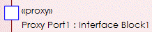
Create new Proxy Ports through the  Proxy Port button on the diagram's tab: click the Proxy Port button, and then click the required item:
Proxy Port button on the diagram's tab: click the Proxy Port button, and then click the required item:• The owning Block (or diagram background if Block is not shown)
• A Block Property whose type is a Block or Interface Block.
• A port whose type is a Block or Interface Block.
Note that if you create a Proxy Port on a Block Property, the Proxy Port is created as a child of the Block Property's type. The Proxy Port that appears on the diagram is a virtual redefinition of the Proxy Port on the type. For more information about redefinitions of Proxy Ports, click here
To populate missing Proxy Ports: right-click the owning Block, Block Property or port, point to Populate, point to Nodes, and then click Proxy Ports.
The view options of a Proxy Port are set through the Port entry on the View Options dialog.
Standard Port (UML Item)

Create Standard Ports through the  Standard Port button on the diagram's tab: click the Standard Port button, and then click the required item:
Standard Port button on the diagram's tab: click the Standard Port button, and then click the required item:The owning Block (or diagram background if Block is not shown)
A Block Property whose type is a Block.
A port whose type is a Block.
Add an existing Standard Port to an Internal Block Diagram by clicking the Standard Port button on the diagram's tab, right-clicking the owning Block (or diagram background if Block is not shown), Block Property or port, and then from the dialog selecting the Standard Port you want to add.
Standard Port button on the diagram's tab, right-clicking the owning Block (or diagram background if Block is not shown), Block Property or port, and then from the dialog selecting the Standard Port you want to add.To populate missing Standard Ports: right-click the owning Block, Block Property or port, point to Populate, point to Nodes, and then click Standard Ports.
The view options of a Standard Port are set through the Port entry on the View Options dialog.
Like all other diagrams, an Internal Block Diagram can show Requirements, Problems, Rationales and traceability links.
Allocate
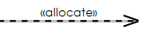
Create new Allocate relationships through the  Allocate button on the diagram's tab: click the Allocate button, click the item that is allocated to, and then click the item that is allocated from. If a popup menu appears, click New or select an existing Allocate relationship to add.
Allocate button on the diagram's tab: click the Allocate button, click the item that is allocated to, and then click the item that is allocated from. If a popup menu appears, click New or select an existing Allocate relationship to add.To populate all Allocate relationships that are missing from the diagram: right-click in free space, point to Populate, point to Links, and then click Allocates. To populate only those Allocate relationships that relate to an item on the diagram, right-click the item, point to Populate, point to Links, and then click Allocates.
Copy
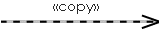
Create new Copy relationships through the  Copy button on the diagram's tab: click the
  Copy button, click the slave Requirement, and then click the master Requirement. If a popup menu appears, click New or select an existing Copy relationship to add.
Copy button on the diagram's tab: click the Copy button, click the slave Requirement, and then click the master Requirement. If a popup menu appears, click New or select an existing Copy relationship to add.To populate all Copy relationships that are missing from the diagram: right-click in free space, point to Populate, point to Links, and then click Copies. To populate only those Copy relationships that relate to a Requirement on the diagram, right-click the item, point to Populate, point to Links, and then click Copies.
Derive Reqt
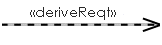
Create new Derive Reqt relationships through the  Derive Reqt button on the diagram's tab: click the Derive Reqt button, click the derived Requirement, and then click the Requirement from which the Requirement you first clicked is derived. If a popup menu appears, click New or select an existing Derive Reqt relationship to add.
Derive Reqt button on the diagram's tab: click the Derive Reqt button, click the derived Requirement, and then click the Requirement from which the Requirement you first clicked is derived. If a popup menu appears, click New or select an existing Derive Reqt relationship to add.To populate all Derive Reqt relationships that are missing from the diagram: right-click in free space, point to Populate, point to Links, and then click Derive Reqts. To populate only those Derive Reqt relationships that relate to a Requirement on the diagram, right-click the Requirement, point to Populate, point to Links, and then click Derive Reqts.
Problem
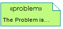
Problem Note button on the diagram's tab: click the  Problem Note button, and then click in free space.
Problem Note button, and then click in free space.Rationale
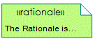
Create new Rationales through the  Rationale Note button on the diagram's tab: click the Rationale Note button, and then click in free space.
Rationale Note button on the diagram's tab: click the Rationale Note button, and then click in free space.Refine (UML Standard Profile)
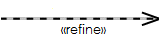
Create new Refine relationships through the  Refine button on the diagram's tab: click the Refine button, click the refining item, and then click the refined item.
Refine button on the diagram's tab: click the Refine button, click the refining item, and then click the refined item.To populate all Refine relationships that are missing from the diagram: right-click in free space, point to Populate, point to Links, and then click Refines. To populate only those Refine relationships that relate to a Requirement on the diagram, right-click the Requirement, point to Populate, point to Links, and then click Refines.
Requirement
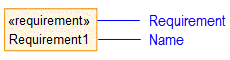
Create new Requirements through the  Requirement button on the diagram's tab: click the Requirement button, and then click in free space.
Requirement button on the diagram's tab: click the Requirement button, and then click in free space.To add an existing Requirement to the diagram through the Requirement button on the diagram's tab: click the Requirement button, right-click in free space, and then select the Requirement you want to add to the diagram.
Requirement button on the diagram's tab: click the Requirement button, right-click in free space, and then select the Requirement you want to add to the diagram.Requirement Extension
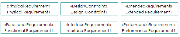
Create new Requirement Extensions through the appropriate Requirement Extension button on the diagram's tab: click the appropriate Requirement Extension button, and then click in free space. The following non-normative Requirement Extension buttons are available:
 Design Constraint
 Extended Requirement
 Functional Requirement
 Interface Requirement
 Performance Requirement
 Physical Requirement
To add an existing Requirement Extension to the diagram through the appropriate Requirement Extension button on the diagram's tab: click the appropriate Requirement Extension button, right-click in free space, and then select the Requirement you want to add to the diagram.
Requirement Extension button on the diagram's tab: click the appropriate Requirement Extension button, right-click in free space, and then select the Requirement you want to add to the diagram.Satisfy
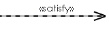
Create new Satisfy relationships through the  Satisfy button on the diagram's tab: click the Satisfy button, click the item that satisfies the Requirement, and then click the satisfied Requirement.
Satisfy button on the diagram's tab: click the Satisfy button, click the item that satisfies the Requirement, and then click the satisfied Requirement.To populate all Satisfy relationships that are missing from the diagram: right-click in free space, point to Populate, point to Links, and then click Satisfies. To populate only those Satisfy relationships that relate to an item or Requirement on the diagram, right-click the item or Requirement, point to Populate, point to Links, and then click Satisfies.
Trace (UML Standard Profile)
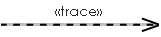
Create new Trace relationships through the  Trace button on the diagram's tab: click the Trace button, click the tracing item, and then click the traced item.
Trace button on the diagram's tab: click the Trace button, click the tracing item, and then click the traced item.To populate all Trace relationships that are missing from the diagram: right-click in free space, point to Populate, point to Links, and then click Traces. To populate only those Trace relationships that relate to an item on the diagram, right-click the item, point to Populate, point to Links, and then click Traces.
Verify
Create new Verify relationships through the  Verify button on the diagram's tab: click the Verify button, click the item that verifies the Requirement, and then click the verified Requirement.
Verify button on the diagram's tab: click the Verify button, click the item that verifies the Requirement, and then click the verified Requirement.To populate all Verify relationships that are missing from the diagram: right-click in free space, point to Populate, point to Links, and then click Verifies. To populate only those Verify relationships that relate to an item or Requirement on the diagram, right-click the item or Requirement, point to Populate, point to Links, and then click Verifies.
The following sections provide information about how an Internal Block Diagram is used in the model. For more information about a SysML item - click it.
Owned by

Creates or shows these items
Actor (UML item) Dependency (UML item) Interface (UML item) Standard Port (UML item)
Like all other diagrams, an Internal Definition Diagram can show Requirements, Problems, Rationales and traceability links:
SysML Properties
• allocatedFrom - lists source items that are linked through Allocate relationships (on Allocated tab when item is allocated).
• allocatedTo - lists target items that are linked through Allocate relationships (on Allocated tab when item is allocated).
• owner - lists the Block that owns the Internal Block Diagram.