• Diagram products that are based on UML diagrams, such as, Class Diagrams, Composite Structure Diagrams and Activity Diagrams.
• Table and matrix products that are generated as HTML for viewing in your internet browser, or generated as spreadsheets for viewing in Microsoft Excel.
Diagram Products
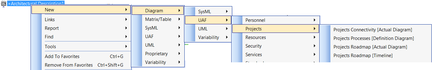
Most diagram products can be created from an Architectural Description: right-click the Architectural Description, point to New > Diagram > UAF > Projects and then click the command for the diagram product type you want to create.
Other diagram products are created from their owning element, for example, when using the UAF Profile you can create a Rs-Pr Resources Processes view from an Architectural Description.
To open a diagram product: double-click the product, or right-click the product and then click Open.
When you want to work with a diagram product type the first time, read the appropriate Help topic and explore the toolbar buttons and commands that are available for the diagram:
• See the reference topic for the product type in the appropriate UAF profile section of the Modeler Help. These topics provide information about the purpose of the product, creating the product, and creating the elements that can appear on the product diagram.
To open the Help topic for a product from Modeler: right-click the product, and then click Help.
• Hover the mouse pointer over each diagram toolbar button to see which elements can be created on the diagram.
• The toolbar buttons allow you to create node and links elements on the product diagram:
◦ For node elements, click the toolbar button, and the click the diagram background or an appropriate element.
◦ For link elements, click the toolbar button, click the source element on the diagram, and then click the destination element on the diagram.
• You can usually add existing elements to a product diagram in the following ways:
◦ Drag the element from a Modeler pane (such as the Packages pane) to the diagram background or owning element.
◦ Click a diagram toolbar button, right-click the diagram background or owning element. Modeler opens a dialog for you to select the element you want to add.
◦ Right-click the diagram background, point to Populate, point to Nodes or Links, and then click the command for the element types you want to add to the product diagram. Modeler typically adds the elements that are scoped to the element that owns the product.
◦ Right-click an element on the product diagram, point to Populate, point to Links, and then click the command for the link type you want to add to the product diagram. Modeler adds the link elements that relate to the element you right-clicked, adding any missing node elements that are required to show the missing link elements.
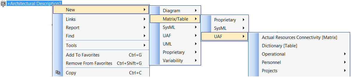
Most table and matrix Products can be created from an Architectural Description: right-click the Architectural Description, point to New > Matrix/Table > UAF and then click the command for the table or matrix product type you want to create.
To open a table or matrix product: double-click the product, or right-click the product and then click Open.
When you want to work with a table or matrix product type the first time, read the appropriate Help topic and explore the commands that are available for the product:
• Right-click the product, point to Set, and see which commands are available for the product.
By default, Modeler generates a table or matrix product as HTML for viewing in your internet browser, but you can generate tables and matrices as spreadsheets for viewing in Microsoft Excel.
• When you create a table or matrix product, Modeler does not open the table or matrix.
• Each time you open a table or matrix product, Modeler uses the current data in the model to generate the table or matrix.
• To set up a model to generate tables and matrices as spreadsheets: in the Packages pane, right-click the Model, point to Tools > Options, click Matrix/Table Generation Format, and then select Excel.
When the product is created from an Architectural Description, by default, only the Architectural Description that owns the product is used to find data for the product.
To include data from other Architectural Descriptions: right-click the product, point to Set, and then click Analyzed Packages. From the Links Editor, select the Architectural Description packages from which you want to include data.
For table and matrix products you may be able to customize the presentation, for example, change the row and column labels that are used. For more information about customizing a custom table or matrix, see
Overview of custom matrices.
Finding Products
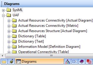
UAF products are shown by type in the Diagrams pane.