You can add existing elements to a product diagram in the following ways:
• Through a drag-and-drop operation
• Through a diagram toolbar button
• Through the populate context menu commands
• Through the Add context menu commands
Adding existing elements through a drag-and-drop operation
Drag valid elements from any Modeler pane to a Product diagram.
You can select and drag multiple elements from the Contents, Results and Favorites panes.
Adding an existing element through a diagram toolbar button
Click the diagram toolbar button, and then right-click the background of the diagram or the owning element on the diagram. From the dialog you can then select the element you want to add.
Adding existing elements through the populate context menu commands
You can populate missing node and link elements on a diagram.
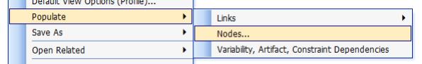
To populate elements: right-click the diagram background or an element on the diagram, point to Populate, point to Links or Nodes, and then click the required command.
Populating node elements from the diagram background
When you populate node elements from the diagram background, Modeler adds node elements of the selected type that are scoped to the element that owns the product.
Populating node elements using the Populate Nodes dialog box
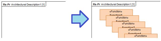
Use the Populate Nodes dialog box to add node elements. Modeler adds node elements of the selected type that are scoped to the element that owns the product.
In this example, the Architectural Description that owns the Rs-Pr Resources Processes [Definition Diagram] also owns five Functions named Function1, Function2, Function3, Function4, and Function5. When we populate Functions from the background of the Rs-Pr Resources Processes [Definition Diagram], Modeler adds the five Functions to the diagram.
Populating link elements from the diagram background
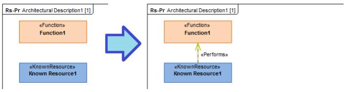
When you populate link elements from the diagram background, Modeler adds link elements of the selected type that are linked between elements that are shown on the diagram. Modeler does not add any nodes to the diagram.
In this example, Person1 and Known Resource1 are linked to Function1 by Is Capable to Perform links. The Rs-Pr Resources Processes [Definition Diagram] shows Person1 and Function1 but not Known Resource1. When we populate Is Capable to Perform links from Person1, Modeler adds the Performs link that links Known Resource1 to Function1.
Populating link elements from a node element
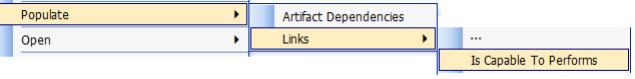
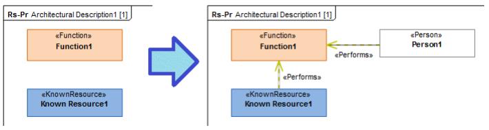
When you populate link elements from a node element, Modeler adds link elements of the selected type that are linked to the element that you right-clicked. Modeler adds any node elements that are required to show the missing link elements.
In this example, Person1 and Known Resource1 are linked to Function1 by Is Capable to Perform links. The Rs-Pr Resources Processes [Definition Diagram] shows Known Resource1 but not Person1 and Function1 When we populate Is Capable To Perform Links from Person1, Modeler adds the Performs link that links the Known Resource1 to Function1. In addition, Modeler also adds Person1 to the diagram so that Function1’s other Performs link can be shown.