Rotation in 3D Mode with Arbortext IsoDraw CADprocess
Clicking the
Rotation 
tool allows you to rotate all the assemblies in a drawing around one of the three axes of the coordinate system or around a free axis. When working with the X, Y or Z axes, click your mouse on the desired axis. The axis will be selected. A free axis stays active for as long as it is visible.
Now click the drawing area. Move the mouse in a circle around the coordinate system origin. While moving the mouse, you can see how the orientation of the drawing changes. During this rotation, the angle of rotation is displayed in the window bar at the bottom.
You can also rotate a selection of assemblies in the same way. You can select the required assemblies using the object window or the
Arrow tool. Once you have activated the
Rotation tool, you can switch to the arrow

cursor temporarily by pressing the CTRL key.
If you now want to rotate the selection around another axis, click the axis in question or define an axis using one of the 3D axis selectors and repeat the rotation procedure described above.
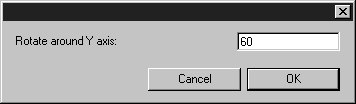
Holding down the SHIFT key when you click on the drawing area or click the selection will result in the following dialog box appearing:
The entry field shows which axis (X, Y, Z or free) is currently selected (Y axis in the dialog box shown). Enter the required number of degrees and confirm by clicking OK. Clicking Cancel closes the dialog box without rotation occurring.
| 3D transformations, such as Rotation, only apply to visible 3D objects by default. If you want 3D transformations to apply to both visible 3D objects and invisible parts inside of 3D objects, you must enable the CADprocess_TransformInvisible3DSubObjects preference setting. See 3D Editing Preferences for instructions.) |