Hide Parts and Explode the Remaining
This part of the exercise involves hiding a number of parts. These parts are not required in the spare part drawing that is to be created.
1. Change the display mode.
Click on the symbol for
HLR
display mode.
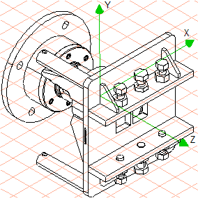
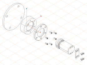
The drawing now appears on the screen as indicated in the figure.
2. All the parts not needed in the spare part drawing are to be hidden.
| All the parts (objects) that are hidden, and therefore have been made invisible, will be ignored during the conversion process to a 2D illustration. |
Select the > menu.
The object window is displayed with the name of the file on the drawing sheet.
3. Holding down the CTRL key, click on the + symbol in front of the file name plate_object.idr.
All of the objects contained in the file are shown.
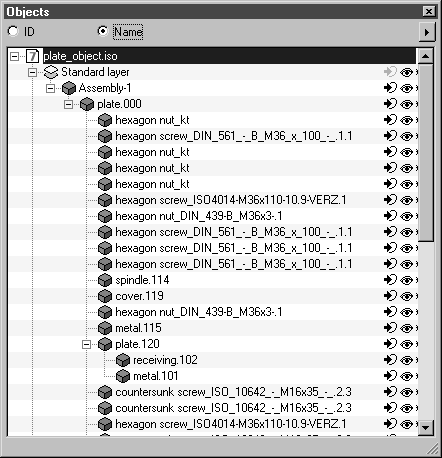
4. Select the button next to Name in the object window.
The object window will now appear as indicated below.
5. Click on the assembly with the name plate.111.
The assembly is highlighted. The assembly contains subassemblies that are shown indented. Once the assembly is selected in the object window, all the relevant parts (subassemblies) in the drawing are selected.
6. Click on the eye symbol next to assembly plate.111 in the object window.
The eye symbol next to the assembly and all its subassemblies closes. None of the parts are now visible in the drawing.
7. The nuts and bolts that form part of the plate are also to be hidden.
Using the arrow cursor, click in the area of a bolt. Holding down the SHIFT key, use the same cursor to click in the area of all the remaining nuts and bolts belonging to the plate (plate.111) one at a time.
The parts are now selected.
8. Select the > menu.
The names of the nuts and bolts are highlighted in the object window.
9. Select the Objects invisible command in the pop-up menu of the object window.
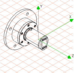
The nuts and bolts that have been selected are hidden.
All of the relevant parts have now been hidden. The drawing now appears on the screen as indicated in the figure.
10. The next step involves spatially separating the remaining parts for the spare part drawing.
Select all the parts using the command code CTRL+A.
11. Click on the symbol for the
Explode assemblies
tool.
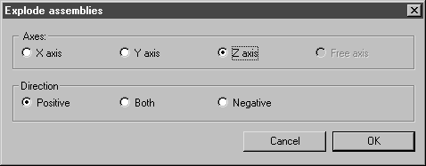
The following dialog box appears.
12. Click the buttons next to Z axis and Positive.
By selecting these options, the selected parts are moved in the direction of the arrow on the Z axis.
13. Confirm the settings by clicking OK.
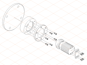
All the parts have now been spatially separated along the Z axis.
14. To ensure that the parts are in their assembly position, a few of them need to be rearranged.
Click the Z axis with the arrow cursor.
The color of the axis changes to red. This indicates that it has been defined as a move axis and is active.
15. Arrange the parts to match the figure.
To do this, select one or more parts with the arrow cursor. When selecting several parts at the same time, e.g. the bolts, hold down the SHIFT key after clicking on the first part.
16. After having selected parts, use the arrow cursor to click in the area of the selected parts. Holding down the mouse button, drag the parts to their intended position.
17. Once this has been done for all the parts, save the file.
| The file in its current state will be used again in the next exercise. |
18. The drawing can now be converted to a 2D illustration for final editing.
To do this, click on the
Convert to 2D illustration
symbol.
The drawing is converted and appears in a new untitled window.
19. Select the new untitled window containing the converted file from the list of open files in the Window menu.
The window is brought to the front and becomes the active window.
20. Save the drawing as plate_compl_explo_2D.idr .
21. You can now draw the threads for the bolts and bores, as well as the center lines.
The figure shows the spare part drawing after editing. The original drawing has also been scaled down here. The file plate_compl_explo_2D.idr with the completed drawing can be found in the Arbortext-IsoDraw-install-path\Tutorial\Tutorial CADprocess folder.