Cut Free the Grease Nipple and Protecting Cap Parts
1. The parts grease nipple (116_grease nipple...) and protecting cap (117_protecting cap...) hidden among the surrounding parts thread plate (103_thread plate...) and tube (101_tube...) are now to be made visible.
To see whether the hidden parts are located within the cutting area, change the display mode.
Click on the symbol for
Wireframe
display mode.
2. Click the symbol for the
3D Cut free shape
tool.
The cursor changes to a lasso

.
3. The drawing needs to be enlarged so that you can accurately select the area to be cut away.
Hold down the CTRL+ALT keys.
The cursor changes into a magnifying glass with a plus sign.
4. Click with your mouse on the area to be cut away.
| The drawing is doubled in size each time the mouse button is clicked. The center point of the drawing is the point where you clicked your mouse. |
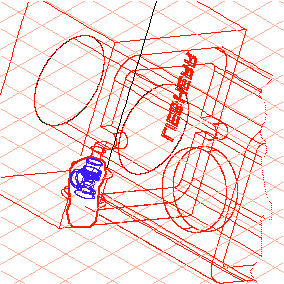
5. The thread plate (103_thread plate...) and tube (101_tube...) parts that are to be cut away must now be selected.
Hold down the CTRL key.
The cursor changes to an arrow

cursor.
6. Click your mouse on the area of the thread plate. While still holding down the CTRL key, hold down the SHIFT key also. Click in the area of the tube.
| When the arrow cursor is positioned over a part, object information is displayed. This makes it easy to locate a part. |
Once the parts have been hit, their contour lines are depicted in red.
7. Release the CTRL and SHIFT keys.
The cursor turns back into the lasso of the active cutting tool.
8. Holding the mouse button down, move your mouse to define the boundary for the cutout in the selected parts.
Set the boundary so that the outer area of the bore in the thread plate is not included.
The figure depicts how the boundary should more or less look.
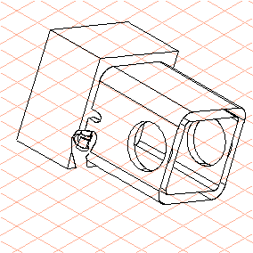
9. Change to
HLR
display mode to view the cutout.
The drawing appears in HLR display mode more or less as depicted in the figure.
10. The drawing can now be converted to a 2D illustration for final editing.
To do this, click on the
Convert to 2D illustration
symbol.
The drawing is converted and appears in a new untitled window.
11. Select the new untitled window containing the converted file from the list of open files in the Window menu.
The window is brought to the front and becomes the active window.
12. Save the drawing as nipple_cut_2D.idr.
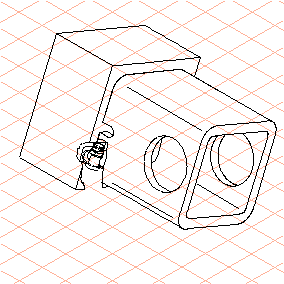
You can now edit the drawing using the tools in Arbortext IsoDraw CADprocess. For example, add edges for the surrounding parts in the cutout section.
The figure depicts the drawing after some detail work. The file nipple_cut_2D.idr with the completed drawing can be found in the Arbortext-IsoDraw-install-path\Tutorial\Tutorial CADprocess folder.