Cut Away the Section of the Drawing that is not Needed
This part of the exercise involves cutting away the section of the drawing tha tis not important for the isometric figure.
1. Click on the symbol for
HLR
display mode.
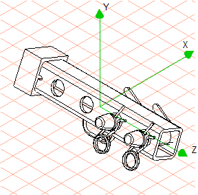
The drawing appears on the screen as indicated in the figure.
The
3D Cut rectangle
tool and
3D Cut free shape
tool cuts away all surfaces and elements irrespective of the spatial orientation of the drawing. In other words, it cuts through the layers of the drawing. To ensure a cut is correctly depicted in all spatial orientations of the drawing, the drawing needs to be moved to an appropriate view for the cutting. This view must be selected so that the cutting is performed parallel to a drawing layer.
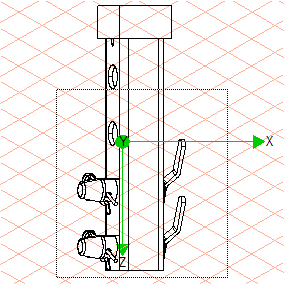
2. In this exercise, the drawing must be rotated into View Y for the cutting.
Select the > > menu.
3. Click the symbol for the
3D Cut rectangle tool.
The cursor arrow is now black and there is a rectangle symbol underneath it.
4. Holding down the mouse button and starting from the left below the first bore in the tube (101_tube...), drag a selection rectangle.
The rectangle must encompass all sections of the drawing below and to the right of the point of origin of the selection rectangle. The figure depicts the drawing in View Y with the selection rectangle.
| All selected areas of objects or surfaces inside the selection rectangle are cut away. If, as in this exercise, nothing is manually selected, all objects and surfaces are selected. |
When you have selected the specified area of the drawing, release the mouse button.
All sections of the drawing within this selection rectangle have been cut away.
5. Select the > > menu.
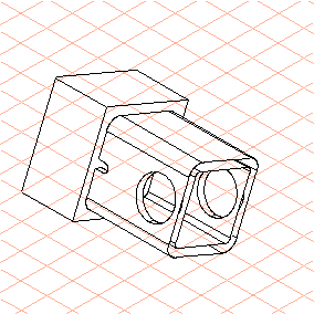
The drawing now appears on the screen more or less as indicated in the figure.