Open the Prepared 3D Drawing
1. Open the file, support.idr, from the Arbortext-IsoDraw-install-path\Tutorial\Tutorial CADprocess folder in the installation folder.
On opening the file, only the coordinate system will be visible. The drawing is out of view because it is not located on the drawing sheet. The drawing has so far only been imported.
|
|
It is often the case with a CAD program that a drawing is a large distance away from the coordinate system. As a result, the drawing is entirely or partially out of view.
|
2. Save the file as support_cut.idr.
3. Click on the symbol for the
Center elements
tool.
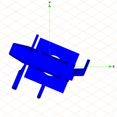
The drawing is then positioned centrally - in relation to its overall extent - above the coordinate system.
The drawing appears on the screen as indicated in the figure.
4. The drawing still has to be converted to the Isometric view top projection. The hidden parts are to be visible in this view after they have been cut free from their surrounding parts.
Select the > > menu.
5. Click on the symbol for the
Extent
tool.
The entire drawing is now displayed on the screen with color rendering in the Isometric view top projection.