Prepare the Imported Drawing
1. Open the file plate.idr from the Arbortext-IsoDraw-install-path\Tutorial\Tutorial CADprocess folder in the installation folder.
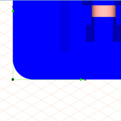
You will then see the coordinate system and part of the drawing in View Z on the drawing sheet. Rendering display mode has been preselected. All parts are displayed with color rendering.
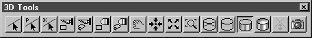
The standard toolbar containing the tools and functions for working in 3D mode also appears adjacent to the attribute window.
| If ;your 3D Tools toolbar does not contain all of the icons in the figure above: a. Select the > menu. b. Select the 3D Tools toolbar from the list, press the Edit button. c. Click on the Factory settings button in the Edit Toolbar dialog and press OK. All the tools in the toolbox and all the menu commands not grayed out can be used in 3D mode. |
2. Save the file as plate_explo.idr.
3. Click on the symbol for the
Extent
tool.
The entire drawing now appears on the screen.
4. The drawing must be rotated into a suitable projection before the parts can be spatially separated for a spare part drawing.
Select the > > menu.
5. Click on the symbol for the
Center elements
tool.
In terms of its extent, the drawing is then located centrally, above the coordinate system.
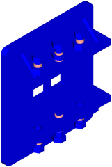
6. Click again on the symbol for the
Extent tool.
The drawing now appears on the screen as indicated in the figure.
The next stage in this exercise involves exploding the nuts and bolts on the upper and lower bars.