To Define the Lattice Region
Define the lattice region as part of the procedure for creating beam-based, 2.5D, formula-driven, custom, and stochastic lattice.
1. Click >  Lattice. The Lattice tab opens.
Lattice. The Lattice tab opens.2. Click the Lattice Region tab.
3. Select one of the following options:
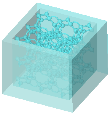
◦ To add lattice inside a volume that you define, and not replace the body with lattice:
1. Clear the Replace body with lattice check box.
2. To define an internal volume for the lattice by selecting a volume region, click the Lattice volume region collector, and hold down the CTRL key while you select the surfaces, quilts, and datum planes that bound the lattice propagation. You can click Details to open the Surface Sets window.
The selected surfaces, quilts, and datum planes should create a closed volume. The arrow should point toward the inside of the volume.
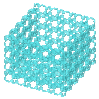
◦ To replace a body with lattice:
1. Select the Replace body with lattice check box.
2. To define the body to replace with lattice, click the Body to replace collector, and select a body.
3. Select one of the following options:
▪ To exclude the shell from the lattice, clear Create shell.
▪ To include the shell in the lattice, select Create shell, and set the following parameters:
1. To set the shell thickness, type a value next to Thickness.
2. To select the side of the lattice on which to create the shell, next to Shell side, select Inside or Outside.
3. To exclude shell surface from the lattice, in the Excluded shell surfaces collector, select the surfaces to exclude.
When you replace a body with lattice: • You cannot choose the lattice volume region. • The Body Options tab is not available. |
4. To process the lattice without geometry that fails to intersect or detach, select the Skip failed geometry check box.
This option is not available for formula-driven lattice.
5. To orient the lattice cells, click the Orientation collector, and select a coordinate system or a build direction analysis. If you select a build direction analysis, the lattice z-direction coincides with the build direction. If the model contains a build direction analysis feature, it will be used automatically as the direction for the lattice. See About the Build Direction.
6. To change the default location of the first lattice cell, click the First cell position box, and in the graphics window select a coordinate system, vertex, or datum point.