To Create 2.5D Lattice
When you create 2.5D lattice, you choose a planar shape that is projected perpendicular to the plane as the lattice cell. The cells propagate to fill the defined area.
1. Click >  Lattice. The Lattice tab opens.
Lattice. The Lattice tab opens.2. Next to Lattice type, select  2.5D, and define the following:
2.5D, and define the following:a. To define the direction with which the z-axis of the cell is aligned, select Z, X, or Y.
b. To define how the lattice cells are propagated in the internal volumes, under Cell Propagation, select one of the following:
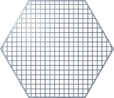
▪ To add lattice cells one after the other in straight lines and layers, click Regular.
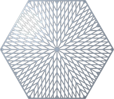
▪ To add lattice cells in a circular pattern, click Quasi-radial, and type a value for Base cell number.
▪ To add lattice cells in herringbone structure, click Herringbone. Herringbone propagation requires a non-zero skew angle.
Skewing angle 30º | Skewing angle 45º |
 | 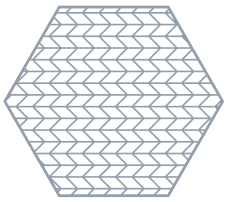 |
c. To set the size of the lattice relative to the current size of the cell, under Cell Scale, type a value, and press ENTER.
d. To define the lattice representation, in the Representation list, select an option:
▪ Full geometry—Accurate appearance, includes all properties. Requires more resources and might cause the system to be slow, particularly when the lattice contains a large number of lattice cells.
▪ Simplified—Lightweight approximation of the lattice.
▪ Homogenized—Creates a quilt to represent the lattice volume. It defines the lattice without actually creating it in the model. Used for dense lattice structures, as it considerably reduces model size and analysis run time.
4. For lattice that does not replace a body, you can define the body to which the feature is added. Click the Body Options tab, and perform one of the following actions:
◦ To add geometry to an existing body, click the body collector, and then select the body to which geometry is added.
◦ To create the feature in a new body, select the Create new body check box. The name of the new body appears in the body collector.
5. Click the Cell Type tab, and perform the following actions:
a. Under Cell Shape, select  Triangular,
  Square,
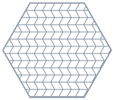
  Hexagonal, or
  Octagonal.
Triangular, Square, Hexagonal, or Octagonal.b. To set the dimensions of the cell, next to Cell size, type the values of the X and Y dimensions of the cell, in the model units.
c. To set the slanting angle of the cell, next to Skewing angle, type a value.
6. Click the Cell Fill tab, and perform the following actions:
a. To set the thickness of the cell wall, type the value in Wall thickness.
b. To create rounds at the concave edges of the cells, select the Round radius check box, and type the radius value. Available for Full geometry representation.

c. To add drain holes to each cell, select the Add drain holes check box, and define the following options:
▪ To define the width of the drain hole, type a value next to Width.
▪ To define the length of the drain hole, type the value next to Length.
▪ To define the space between the drain holes along the z-axis, type a value next to Spacing.
7. Click  OK.
OK.
OK.