About the Build Direction
You must have a Creo Additive Manufacturing license to use build direction analysis.
The build direction is a critical consideration in preparing for 3D printing. Determining the build direction is one of the first steps in design for additive manufacturing, because other steps depend upon it, such as support structures, lattice orientation, and placement of the model on the tray.
You define the build direction in Part mode. In the Model Tree, a Build Direction feature is created, represented by  . A coordinate system whose z-axis indicates the build direction appears in the graphics window.
. A coordinate system whose z-axis indicates the build direction appears in the graphics window.You can use the Build Direction feature to communicate your design intention for these purposes:
• Orient the lattice cells. See To Define the Lattice Region.
• Orient the models on the tray according to the z-axis of the build direction. This applies only to part models, not to assemblies. See the topic To Create a Tray Assembly in the Additive Manufacturing Help.
When you perform a build direction analysis, the analysis examines the part’s surfaces with a normal vector, and maps the surfaces according to rules such as surface area and critical surface angle. The analysis identifies downward-facing surfaces in the part that require support for 3D printing according to two typical angles:
• Critical angles
◦ Surfaces
A downskin surface is a surface with a normal from 0 to the critical angle, measured relative to normal to the tray, that requires support during 3D printing.
◦ Edges
An overhang edge is an edge that requires support during 3D printing, it does not touch a downskin surface, and the angle between the edge and the tray is between 0 and the critical angle.
◦ Vertices
An overhang vertex is a vertex that requires support during 3D printing, and that does not touch a downskin surface or an overhang edge.
• Sub-critical angles—Surfaces with a normal from the critical angle to the sub-critical angle, measured relative to normal to the tray, could suffer from poor surface finish if they are not supported.
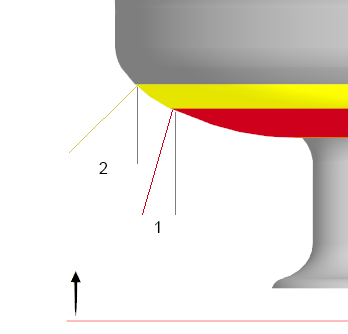
1. Critical angle
2. Sub-critical angle
When you analyze the build direction, you can optimize for the following parameters:
• Downskin area—Minimize the area that requires support for 3D printing
• Support volume—Minimize the volume of the support structures that are required for 3D printing
• Shadow area—Minimize the area that the model projects onto the printing tray (x-y plane)
• Model height—Minimize the height of the model
Construction bodies are not included in a build direction analysis.