Library Modelling Rules
Associated Geometry Components can be attached to the wire harness assembly in the following ways:
• Coordinate System (CSYS) Attachment
• Axis Attachment
Modelling Rules: CSYS Attachment
Use the coordinate system attachment for AGCs that have a coordinate system and do not depend on any other harness geometry. For example, grommets.
|
Z-axis along segment axis 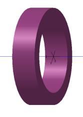 |
Z-axis perpendicular to segment axis 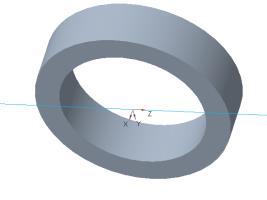 |
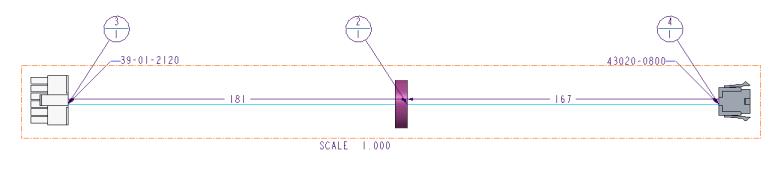
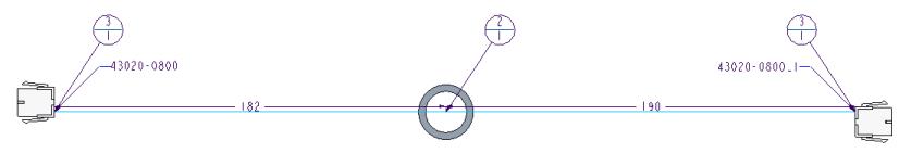
The orientation of the coordinate system of the AGC determines how the AGC will be placed in the harness manufacturing drawing. HMX aligns the z direction of the coordinate system with the segment.
The following image shows the drawing of the harness assembly with the purple grommet that has the z axis along the segment axis.
The following image shows the drawing of the harness assembly with the grey grommet that has the z axis perpendicular to the segment axis.
Modelling Rules: Single Axis Attachment
Ensure the single axis associated geometry components in your 3D harness assembly are modelled as per the following rules:
1. Define routing axis—Ensure the component has a datum axis through all orifices. This datum axis is also called the routing axis as all wires and cables in the harness assembly are routed through these axes.
2. Define bend angle—In the Parameters dialog box, add the feature parameter BEND_ANGLE for the routing axis and define the following attributes
◦ Type – Real Number
◦ Value – Angle in degrees measured clockwise from the entry to the exit orifice. The value is zero for single axis attachment AGCs.
• The parameter name is case sensitive. • The angle value can be determined by using the > >  Angle. Angle. |
3. Specify entry orifice—Add a datum point on the routing axis at the orifice that you want to specify as the entry orifice, offset within the body of the component. You can name this datum point as ORIENT_POINT. Typically, this is the orifice with the largest diameter. Position the datum point ORIENT_POINT offset from the entry orifice.
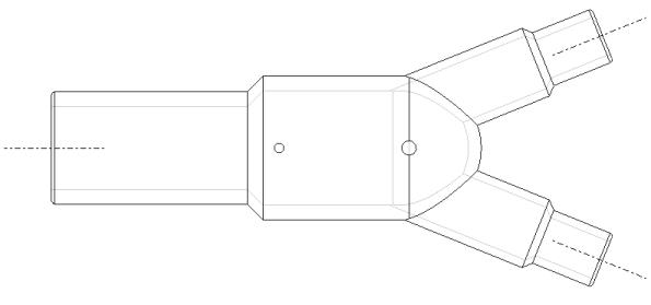
Modelling Rules: Multi Axis Components
Ensure the multi-axis associated geometry components in your 3D harness assembly are modelled as per the following rules:
1. Define routing axes—Ensure the component has a datum axis through the center of all orifices. This datum axis is also called the routing axis as all wires and cables in the harness assembly are routed through this axis.
2. Define bend angle—Add the parameter BEND_ANGLE for all routing axes in the  Parameters dialog box and define the following attributes:
Parameters dialog box and define the following attributes:◦ Type—Real number
◦ Value—Angle in degrees measured clockwise from the entry to the exit orifice.
• The parameter name is case sensitive. • The angle value can be determined by using the > > Angle. |
3. Designate entry orifice—Add a datum point on the routing axis at the orifice that you want to specify as the entry orifice. You can name this datum point as ORIENT_POINT. Typically, this is the orifice with the largest diameter. Position ORIENT_POINT offset from the entry orifice.