About Harness Manufacturing Workflow
The following process automatically generates a manufacturing drawing from the 3D harness:
1. Validate harness—The 3D harness or the harness part is validated for the number of supported connectors and wires.
2. Extract harness information—The harness information is extracted from the routed cabling harness. This extracted information includes component positions, wire segments, wire lengths, branching points, and cosmetic features.
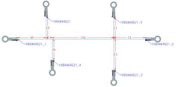
3. Generate the topology—The extracted harness information is used to derive the topology of the 3D harness. The harness topology is a straight-line representation of the physical harness. It is dimensioned and annotated with component views and reference designators. The following figure shows a 2D topographical representation of a 3D wire harness model.
4. Flatten the harness—A full-scale flattened harness drawing based on the shortest routing path of the harness is generated from the topology. HMX tries to fit the flattened harness into the selected drawing template without overlapping the branches. The longest chain of the branch segments is drawn as a horizontal line in the 2D representation.
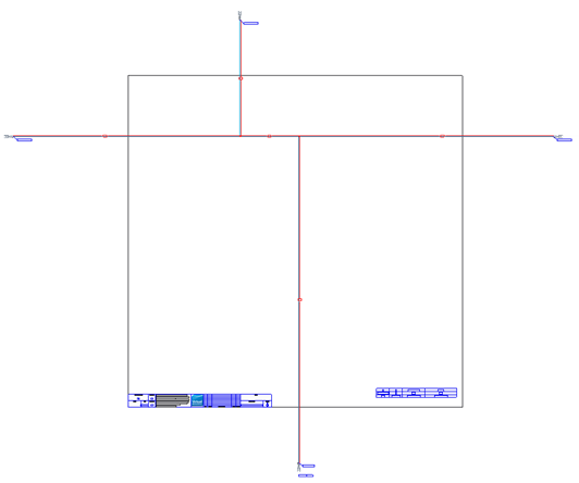
If the harness drawing is too large to be contained in the selected drawing template, a warning message is displayed. The following figure shows an oversized wire harness representation. The harness is too large to fit in the selected drawing sheet template.
You can do the following to fit the 2D topographical representation in the drawing template:
◦ Click Bend to Fit to bend the long branches by 90o.
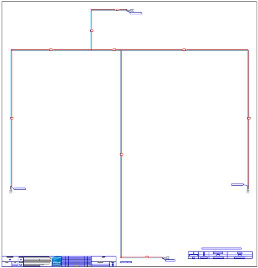
The following figure shows the harness representation when Bend to Fit is selected.
If you click Variable sheet size, only the vertical branches are bent. |
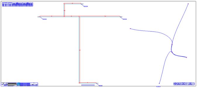
The following figure shows the harness representation when both Bend to Fit and Variable sheet size options are selected. The vertical branch of the harness is bent by 90o to enable the harness to fit onto the selected drawing sheet.
◦ Reduce the scaling factor.
◦ Select a larger drawing template.
You can modify the settings and reflatten to generate a manufacturing drawing for the 3D harness.