To Create HSM 4 Axis Rotary Rough Sequences
Define a 4-axis Rotary rough sequence to generate roughing toolpaths on complex rotary parts.
Ensure that the active operation references a 4 or 5 axis Mill or Mill/Turn work center.
|
|
The  HSM 4 Axis Rotary Rough command with the Mill/Turn work center is available when you have both the Complete Machining and ModuleWorks-based Mold Machining licenses. HSM 4 Axis Rotary Rough command with the Mill/Turn work center is available when you have both the Complete Machining and ModuleWorks-based Mold Machining licenses. |
1. Click > HSM 4 Axis Rotary Rough in the High Speed Milling group. The Rotary Rough tab opens.
HSM 4 Axis Rotary Rough in the High Speed Milling group. The Rotary Rough tab opens.2. Click  Tool Manager or select
  Edit Tools from the Tool list to open the Tools Setup dialog box and add a new cutting tool or change tool parameters. The tool list only includes tools that are valid for the step.
Tool Manager or select Edit Tools from the Tool list to open the Tools Setup dialog box and add a new cutting tool or change tool parameters. The tool list only includes tools that are valid for the step.To show tools for the current step and the active head on the machine tool, set the INCLUDE_ALL_TOOLS_IN_LIST option to YES. |
The supported tools for this sequence are as follows:
◦ End Mill (default)
◦ Ball Mill
◦ Bull Nose Mill
Alternatively, right-click in the graphics window and select Tools.
3. To preview the cutting tool and its orientation in the graphics window, click  Tool Preview next to the Tool list.
Tool Preview next to the Tool list.The Tool Preview button becomes available after you select a tool. |
Alternatively, right-click the graphics window and select the Tool Preview option on the shortcut menu. After you select a tool, the Tool Preview option is available on the shortcut menu of the graphics window.
To exit the tool preview, right-click the graphics window and select Cancel tool preview from the shortcut menu or click Tool Preview again.
Tool Preview again.4. To change the coordinate system that defines the orientation of the step, click the collector adjacent to  and select a coordinate system. If the operation coordinate system differs from the step coordinate system, right-click the collector for the following commands:
and select a coordinate system. If the operation coordinate system differs from the step coordinate system, right-click the collector for the following commands:◦ Default—Replaces the selected coordinate system with the default reference. The default is the orientation that is copied from the previous step or from the operation.
◦ Information—Displays the information of the selected coordinate system.
If your work center setup has two spindles, choose Main Spindle or Sub Spindle from the list, and select a coordinate system each for the main and sub spindle.
The sub spindle is available when you have both the Complete Machining and ModuleWorks-based Mold Machining licenses. After you specify a coordinate system for an NC sequence, it remains in effect until you change it. |
Alternatively, right-click the graphics window and select Orientation from the shortcut menu.
5. Define the options in the following tabs:
◦ Link
◦ Options
◦ Process
6. Click  to open a separate CL Data window.
to open a separate CL Data window.7. Click  to get a dynamic preview of the toolpath in the graphics window.
to get a dynamic preview of the toolpath in the graphics window.8. After you define the mandatory step elements, select a command for toolpath validation:
◦ To play the toolpath, click the arrow next to  and select .
and select .◦ To recompute the toolpath, click the arrow next to and select  .
.
and select .◦ To perform gouge checking against surfaces of the reference part, click the arrow next to and select  .
.
and select .◦ To view the simulation of material removal as the tool is cutting the workpiece, click the arrow next to and select  . The Material Removal tab with integrated simulation environment opens.
and select . The Material Removal tab with integrated simulation environment opens.9. Select one of the following options to complete the sequence:
◦ Click  to save the changes.
to save the changes.◦ Click  to pause the process and use one of the asynchronous tools or click
  to resume.
to pause the process and use one of the asynchronous tools or click to resume.◦ Click  to cancel the changes.
to cancel the changes.Reference Tab
Select the reference part and stock reference. Optionally, define the machining area and containment loops.
Define the following options:
• Reference part—Select a rotary part to use for the rotary roughing step.
If the manufacturing assembly contains only a single reference part, it is selected by default. For multiple reference parts, you must select the required reference part to machine. |
Alternatively, right-click the graphics window and select Reference part from the shortcut menu.
• Stock reference—Select a stock reference. For single or multiple workpieces, Workpiece is the default option . If there is no workpiece, Bound cylinder is the default option .
◦ Workpiece—Define a workpiece to use as a stock reference.
If the manufacturing assembly contains only a single workpiece, it is selected by default. For multiple workpieces, you must select the required workpiece. |
◦ Bound cylinder—Use an automatically created bounding cylinder as a stock reference for the selected reference part.
◦ Rough stock file—Select a rough stock file to use as a stock reference.
◦ Stock model—Select a stock model to use as a stock reference.
Alternatively, right-click the graphics window and select Stock reference from the shortcut menu and then select Workpiece, Bound cylinder, or Rough stock file.
• Machining Area—Set the following options, if required:
◦ Axial—Enter the axial limit to limit the machining area along the axis of rotation.
▪ Start—Enter the axial lower limit for the machining area.
▪ End—Enter the axial upper limit for the machining area.
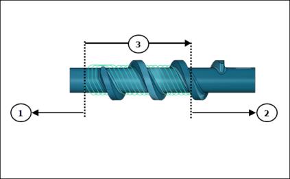
1. Axial Start
2. Axial End
3. Axial Machining Area
◦ Radial—Enter the radial limit to limit the machining area along the diameter of the part.
▪ Start—Enter the radial lower limit for the machining area.
▪ End—Enter the radial upper limit for the machining area.
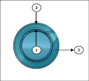
1. Radial Start
2. Radial End
3. Radial Machining Area
• Containment Loops—Optionally, select individual closed loops in the collector or click Details and select chains of loops. If the selected loops do not lie on the reference part surfaces, they are projected normally on the reference part surfaces and the areas inside the loops are machined.
Alternatively, right-click the graphics window and select Containment Loops from the shortcut menu.
Click  to flip the containment area for inverting the machining side and creating toolpath outside the selected containment loops. becomes available if you have selected a closed loop.
to flip the containment area for inverting the machining side and creating toolpath outside the selected containment loops. becomes available if you have selected a closed loop.
Parameters Tab
Specify the required manufacturing parameters. You can also click  to copy parameters from an earlier step or click
  to edit parameters specific to Rotary rough sequence. By default, the required parameters for the selected tool are defined by relations that you can modify from the Relations dialog box.
to copy parameters from an earlier step or click to edit parameters specific to Rotary rough sequence. By default, the required parameters for the selected tool are defined by relations that you can modify from the Relations dialog box.Alternatively, right-click the graphics window and select Parameters from the shortcut menu.
For more information on parameters specific to a Rotary rough sequence, see Rotary Rough Sequence and Rotary Finish Sequence Parameters.
Clearance Tab
Optionally specify the following:
• Retract—Tool is retracted automatically based on the defined value of RAPID_DISTANCE.
• Start and End Points—Specify the Start point and End point for the toolpath.
Alternatively, right-click the graphics window and select Start Point and End Point from the shortcut menu to select start and end points of the toolpath.
Axis Control Tab
Define the tool tilt options.
Set the following options:
• Axis of rotation—Select Z axis or Custom axis.
◦ Z axis (default)—It is the same z-axis of the step orientation. The tool is normal to the z-axis.
◦ Custom axis—Select an axis around which the tool tilts. The tool is normal to the selected custom axis.
• Cone angle—Enter the angle between the rotational axis and outer line of the cone. The tool orientation is normal to the specified value.
Link Tab
Define the connection types within a group, between groups, between slices, or between regions.
• Link within a group—Define the connection types between the cuts in a single group:
◦ Direct—Uses the shortest connection without any retracting movements.
◦ Retract to clear distance (default)—Uses the CLEAR_DIST parameter for retracting the tool and connecting to the next cut within a group.
◦ Retract to rapid distance—Uses the RAPID_DISTANCE parameter for retracting the tool and connecting to the next cut within a group.
• Link between groups—Define a connection type between different groups within a single region on the same cutting layer.
◦ Direct—Uses the shortest connection without any retracting movements for connecting different groups.
◦ Retract to clear distance—Uses the CLEAR_DIST parameter for retracting the tool and connecting to the next group.
◦ Retract to rapid distance (default)—Uses the RAPID_DISTANCE parameter for retracting the tool and connecting to the next group.
• Link between slices—Define a connection type between the cutting depths within the same region.
◦ Direct—Uses the shortest connection without any retracting movements for connecting the next slice.
◦ Retract to clear distance (default)—Uses the CLEAR_DIST parameter for retracting the tool and connecting to the next slice.
◦ Retract to rapid distance—Uses the RAPID_DISTANCE parameter for retracting the tool and connecting to the next slice.
• Link between regions—Define a connection type between different regions.
◦ Direct—Uses the shortest connection without any retracting movements for connecting different regions.
◦ Retract to clear distance—Uses the CLEAR_DIST parameter for retracting the tool and connecting to the next region.
◦ Retract to rapid distance (default)—Uses the RAPID_DISTANCE parameter for retracting the tool and connecting to the next region.
Options Tab
Open a part or assembly to use as a cutting tool adapter. Alternatively, click  to copy cutting tool adapter from another step.
to copy cutting tool adapter from another step.Tool Motions Tab
To create a Goto Point tool motion, select Goto Point. For more information, see To Create a Goto Point Tool Motion.
To insert a CL command along the toolpath, select CL Command. For more information, see To Insert a CL Command for Tool Motions.
The Tool Motions tab is visible only when you define machining references. |
Process Tab
Use any of the following options for the machining step:
• Calculated Time—Click  to automatically calculate the machining time for the step. The Calculated Time box shows the time.
to automatically calculate the machining time for the step. The Calculated Time box shows the time.• Actual Time—Specify the machining time.
Properties Tab
Specify the name or comments for the step.
• Name—Displays the name of the step. You can type another name.
• Comments—Type the comments associated with the step in the text box or use the following options:
◦  —Read in an existing text file containing step comments and replace any current step comments.
—Read in an existing text file containing step comments and replace any current step comments.◦  —Insert the contents of an existing text file of step comments at the cursor location. Preserve any current step comments
—Insert the contents of an existing text file of step comments at the cursor location. Preserve any current step comments◦  —Save current step comments in a text file.
—Save current step comments in a text file.◦  —Accept the current step comments.
—Accept the current step comments.