Rotary Rough Sequence and Rotary Finish Sequence Parameters
Rotary Rough and Rotary Finish Parameters for Cut Depth and Allowances
• MAX_STEP_OVER—Specify the maximum distance between the successive passes. Maximum step over is calculated by default as you select a tool.
Default: Based on internal relation after defining tool.
• STEP_DEPTH—Specify the incremental depth of each pass. The STEP_DEPTH value must be greater than zero. Step depth is calculated by default as you select a tool.
Default: Based on internal relation after defining tool.
• STOCK_ALLOW—Define the amount of stock to leave on all the machining surfaces.
Default: 1 (Rotary Rough Step), 0 (Rotary Finish Step)
• FILTER_TYPE—Select the type of region to filter out while machining. It is specified in relation with the threshold percentage of the tool diameter. It is used to avoid machining of unnecessary regions.
Default: INSCRIBED_CIRCLE
INSCRIBED_CIRCLE—Indicates that the maximum region width filtered is a circle diameter, which is inscribed into toolpath within such a region.
• THRESHOLD_VALUE_PERCENT—Specify the threshold value in percent of the tool diameter. This value determines the width of a region to be filtered out while machining.
Default: 0 percent
This parameter works in combination with the FILTER_TYPE parameter.
• NUMBER_INTERMEDIATE_SLICES—The intermediate slice is a Profile slice between the successive rough slices. Specify the number of intermediate slices to be created.
Default: 0
It does not apply to horizontal and vertical geometry.
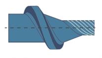
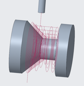
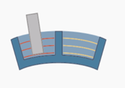
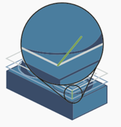
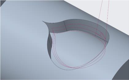
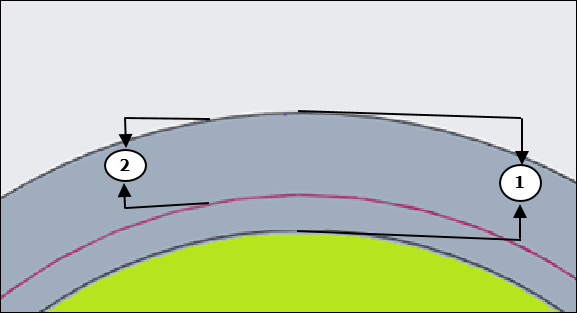
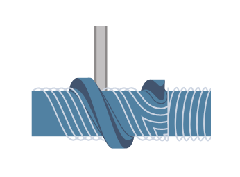
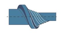
The following image indicates the intermediate slices generated on the inclined surface between the two consecutive roughing slices. No intermediate slice is generated on the horizontal surface.
NUMBER_INTERMEDIATE_SLICES is set to 3:
1. Rotary rough slice
2. Three intermediate slices generated between two rough slices
• INTERMEDIATE_DETECT_THICK_THAN—It is the threshold value to keep or remove the intermediate slices. It avoids intermediate profile slices where amount of stock material is less than the specified threshold value.
1. Specified threshold value
Trimming is performed from the bottom to the top.
Trimming is performed as follows:
◦ If DETECT_THICKER_THAN is 0, filtering is performed using an imposed value (1.25*cutting tolerance).
◦ If DETECT_THICKER_THAN is greater than 0, slices are filtered within the threshold value.
Default: 0
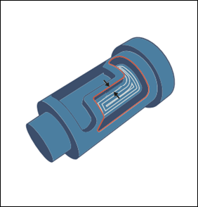
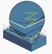
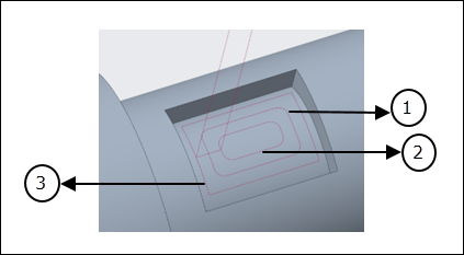
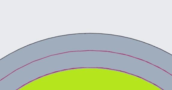
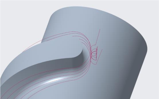
The following toolpath is generated when:
◦ INTERMEDIATE_DETECT_THICK_THAN is set to 0 considering imposed value as 1.25*cutting tolerance.
◦ NUMBER_INTERMEDIATE_SLICES is set to 3.
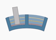
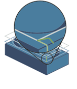
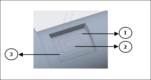
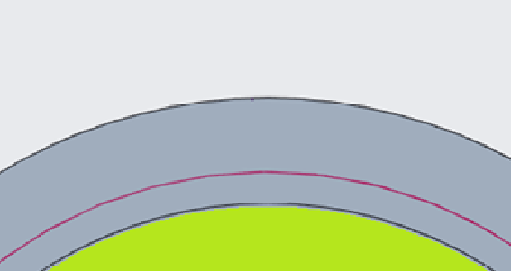
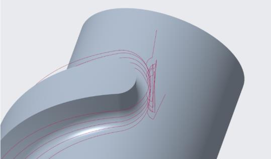
When INTERMEDIATE_DETECT_THICK_THAN is set to 2 and NUMBER_INTERMEDIATE_SLICES is set to 3, the following toolpath is generated:

In such a case, some intermediate passes are removed where the amount of stock material is less than the specified INTERMEDIATE_DETECT_THICK_THAN value.
• MAX_DISCRETIZ_STEP—Specifies the maximum permissible distance between two points in the toolpath.
If the distance between two points in the toolpath is more than MAX_DISCRETIZ_STEP, intermediate points are added in such a way that the distance between two points is always lesser than MAX_DISCRETIZ_STEP.
If no value is specified for MAX_DISCRETIZ_STEP (default), only the tolerance value is used to generate the tool path points.
1. MAX_DISCRETIZ_STEP
• CONTAINMENT_OFFSET—Creates an offset toolpath inside the containment loops by the specified value. For 0 value, there is no offset and the cut is created up to the boundaries of the containment loops.
Default: 0
Negative values are not supported. |
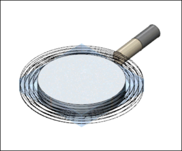
• ADDITIONAL_CUTS_ON_FLOOR—If set to NO (default), this parameter creates constant step depth cuts with no additional cut on the floor. In such cases, stock may remain on the cylindrical or conical surfaces, which can be more or less than the user-defined stock.
If set to YES, this parameter creates an additional cut on each cylindrical or conical surfaces along with the constant step depth cuts, maintaining the user-defined stock. The total number of generated cuts are not distributed equidistantly.
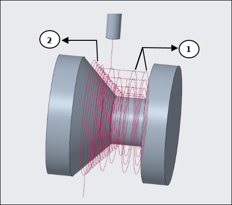
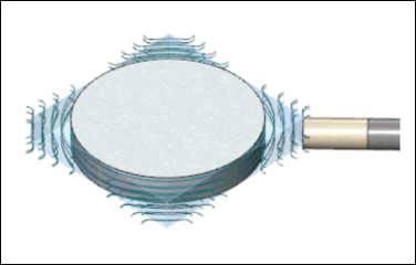
For example, when ADDITIONAL_CUTS_ON_FLOOR is set to YES, additional cuts on each cylindrical surface along with constant step depth cuts are generated as shown in the following image:
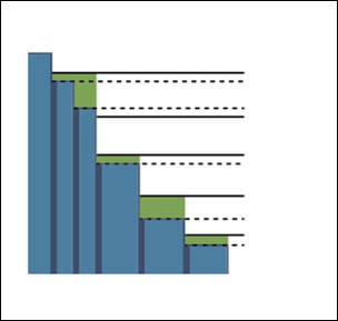
The solid lines represent STEP_DEPTH cuts and dotted lines represent ADDITIONAL_CUTS_ON_FLOOR in the image.
The ADDITIONAL_CUTS_ON_FLOOR parameter is not supported in a Rotary finish step with FINISH_OPTION set to FLOOR_FINISH. |
• SHORT_MOVE_THRESHOLD—Specify the threshold value to segregate short or long moves based on the toolpath length.
Default: 0

1. Length of the toolpath move
• SHORT_MOVE_FILTER—Filters the cuts that have length smaller than the specified value of SHORT_MOVE_THRESHOLD.
The following options are available:
◦ OPEN_CONTOURS—Filters the open loop short moves.
◦ CLOSE_CONTOURS—Filters the close loop short moves.
◦ BOTH_CONTOURS—Filters both open and close loop short moves.
Default: OPEN_CONTOURS
• TRIM_GAP_THRESHOLD—In a Rotary rough step, due to the stock definition, the toolpath is trimmed according to the shape of the stock creating gaps within the toolpath. In a Rotary finish step, due to gaps within the machining surfaces, gaps are generated within the toolpath also.
Specify the threshold value to segregate small or large gaps based on the gap size within the toolpath.
For default value, all gaps are skipped and relinked.
Default: 0
For defined value, the smaller gaps than the threshold values are connected, and the tool stays down. Only the bigger gaps than the threshold value are skipped and relinked.
For example:
◦ When threshold value is 0, all gaps are skipped and relinked.
◦ When the set value is greater than the threshold value of small gap size, smaller gaps are avoided, and the tool stays down. Only the big gaps are skipped and relinked.
Rotary Rough and Rotary Finish Parameter for Cutting Motions
• MACHINE_BY—Select one of the following machining options:
◦ REGIONS—Every region is separately machined one after another.
◦ LEVELS—All regions are simultaneously machined in successive levels.
Rotary Rough and Rotary Finish Parameters for Entry/Exit Motions
• CLOSED_AREA_ENTRY—Specify the entry method for closed areas.
The following options are available:
◦ AUTOMATIC—Tool takes the best suited entry for closed area.
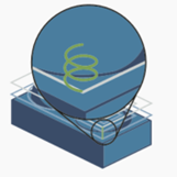
◦ HELICAL—Tool enters a closed area by following a helical trajectory. The diameter of the helix is specified by the HELICAL_DIAMETER_PERC parameter.
◦ LINE_RAMP—Tool enters a closed area by following an angular line.
◦ ZIG_ZAG_RAMP—Tool enters a closed area by following an angular line in a zig-zag motion.
◦ PROFILE_RAMP—Tool enters a closed area by following the shape of the toolpath contour.
Default: AUTOMATIC
For Rotary Finish steps, the CLOSED_AREA_ENTRY options are applicable only when FINISH_OPTION is set to FLOOR_FINISH. |
• RAMP_ANGLE—Specify the angle with which the tool enters the next slice or pass.
Default: 5
• HELICAL_DIAMETER_PERC—Specify the maximum allowed helix diameter in percent of the tool diameter. This is applicable for helical entry of the tool.
Default: 80 percent
• RAPID_DISTANCE—Specify the distance from which the tool retracts or approaches at a rapid feed along the axis. Rapid distance includes the clear distance.
Default: 20 mm
• AIR_MOVE_SAFETY_DIST—It is the minimum distance between the aerial movements of the tool and reference part surfaces to avoid collision.
Default: 10 mm
Rotary Rough and Rotary Finish Parameters for Machine Settings
• SMOOTH_RADIUS—Specify the radius for filleting or for smooth corner machining all the intermediate passes.
This parameter generates smooth radius for intermediate passes only. The value must be greater than 0 and less than the MAX_STEP_OVER value.
Default: -
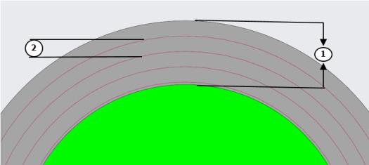
The following image indicates the final pass and intermediate passes when the SMOOTH_RADIUS value is 6 and FINAL_PASS_SMOOTH_RADIUS value is 0.
1. Intermediate Pass
2. Intermediate Pass
3. Final Pass
• FINAL_PASS_SMOOTH_RADIUS—Specify the radius for filleting or for smooth corner machining the final pass.
This parameter generates smooth radius for final pass only. The value must be greater than 0 and less than the MAX_STEP_OVER value.
Default: 0
To generate smooth radius on final pass, the value must be greater than 0 and lesser than the MAX_STEP_OVER value.
When specified value is greater than 0, this parameter works only when the defined value of SMOOTH_RADIUS is greater than 0. |
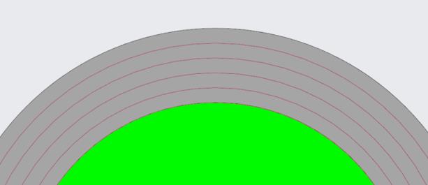
The following image indicates the final pass and intermediate passes when SMOOTH_RADIUS value is 3 and FINAL_PASS_SMOOTH_RADIUS value is 6.
1. Intermediate Pass
2. Intermediate Pass
3. Final Pass
Rotary Rough Parameters
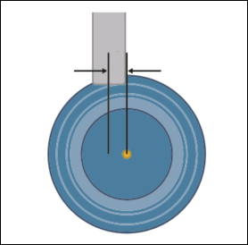
• TOOL_AXIS_OFFSET—Allows rotary rough machining with an axis offset. The tool centerline is offset from the rotation axis of the workpiece.
This parameter enables the tool to cut properly with the cutting edges and not the tool center. Hence, you can achieve more stable cutting speeds and close-to-diameter cutting with non-spherical tools.
The offset is always in the opposite direction to the rotation direction and automatically changes position when the rotation direction changes. This change occurs in a linear movement without rotary movement. This prevents damage to the tool and ensures a safe process.
The maximum accepted value cannot exceed the tool radius.
Default: 0
Negative values are not supported. |
When defined TOOL_AXIS_OFFSET value is greater than 0:
When defined TOOL_AXIS_OFFSET value is 0:
• CONNECT_SEGMENTED_TOOLPATH—If set to NO (default), this parameter removes all toolpath segments that do not intersect with the stock.
If set to YES, this parameter connects the segmented contours that partially intersect with the stock.
• ENSURE_FINISH_CUT—If set to NO (default), this parameter generates partial toolpath segments having retracts.
If set to YES, this parameter connects the partial segments and makes a complete cut, minimizing the retracts.
• MIN_ADAPTIVE_STEP_DEPTH—It is the threshold value that determines one of the following:
◦ Addition of an extra cut to make all cuts equidistant and leaving no material on flat areas.
◦ No addition of an extra cut. Instead generate toolpath with constant step depth, which may leave some material on the flat areas.
If the specified value is smaller than the threshold value, an extra cut is generated. If the specified value is greater than the threshold value, no extra cut is generated.
If an extra cut is generated, the existing step depth cuts and the extra cut are distributed equidistantly.
The MIN_ADAPTIVE_STEP_DEPTH threshold value is determined by the following formula:
Distance between cylinders / Total required cuts
Example 1:
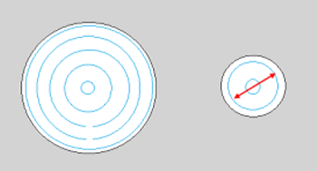
Consider the two cylinders of the following model where the distance between the two cylinders is 25 and the step depth is 6.
1. Distance between 2 cylinders
2. Step depth
The toolpath generates four constant step depth cuts, which leaves some material on the top surface of cylinder 2. To machine this top surface of cylinder 2, one additional depth cut is required. Thus, total five cuts that include four constant step depth cuts and one additional depth cut are required. These five cuts are distributed equidistantly between the 2 cylinders.
In this example, the MIN_ADAPTIVE_STEP_DEPTH threshold value is calculated as 25 divided by 5 with result 5, according to the defined formula.
If the MIN_ADAPTIVE_STEP_DEPTH parameter value is set as 4, which is less than the threshold value of 5, five equidistant cuts are generated leaving no material on the top surface of cylinder 2.
If the MIN_ADAPTIVE_STEP_DEPTH parameter value is set as 7, which is more than the threshold value of 5, the fifth cut is ignored. Four cuts with 6 constant step depth are generated leaving material on the top surface of cylinder 2.
Example 2:
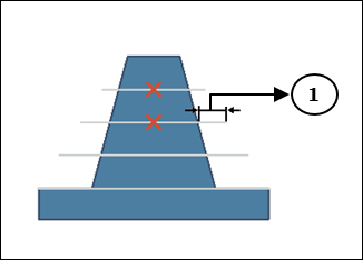
Consider the 2 cylinders of the following model where the distance between the 2 cylinders is 10 and the step depth is 7:
1. Distance between 2 cylinders
2. Step depth
The toolpath generates a single constant step depth cut, which leaves some material on the top surface of cylinder 2. To machine this top surface of cylinder 2, one additional depth cut is required. Thus, total two cuts that include one constant step depth cut and one additional depth cut are required. These two cuts are distributed equidistantly between the 2 cylinders.
In this example, the MIN_ADAPTIVE_STEP_DEPTH threshold value is calculated as 10 divided by 2 with result as 5, according to the defined formula.
If the MIN_ADAPTIVE_STEP_DEPTH parameter value is set as 4.9, which is less than the threshold value of 5, two equidistant cuts are generated leaving no material on the top surface of cylinder 2.
If the MIN_ADAPTIVE_STEP_DEPTH parameter value is set as 5.1, which is more than the threshold value 5, second cut is ignored. Only a single cut with 7 constant step depth is generated leaving material on the top surface of cylinder 2.
• SCAN_TYPE—The following options are available:
◦ OFFSET_ONLY—Defines an offset toolpath along the rotational axis on the entire machining surface. The toolpath is offset from all edges on the machining surfaces.
◦ OFFSET_AND_SPIRAL—Uses a combination of two types of slicing. The toolpath automatically generates spiral cuts till it encounters an obstruction. After encountering an obstruction, the toolpath reverts to an offset strategy.
Rotary Finish Parameters
• CLOSED_LOOP_OVERLAP—Generates no overlapping toolpath in the closed loops.
Default: 0
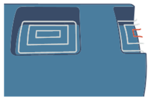
The following toolpath is generated when CLOSED_LOOP_OVERLAP is 0:
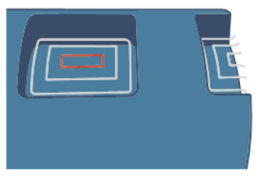
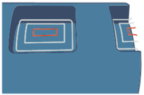
If defined value is greater than 0, generates overlapping toolpath according to the specified value in the closed loops to avoid cutter marks at lead-in and lead-out positions.
The following toolpath is generated when CLOSED_LOOP_OVERLAP is 3:
The CLOSED_LOOP_OVERLAP parameter is not supported with FINISH_OPTION set to FLOOR_FINISH. |
• OPTIMIZED_WALL_STEP_DEPTH—It is the minimum step depth set to finish curves or slanted surfaces.
This parameter is supported only when FINISH_OPTION is set to OPTIMIZED_WALL_FINISH. |
Default: 0.1
• FINISH_OPTION—Specify the machining method to create an optimized tool path.
Applicable for Rotary finish step only.
Default: WALL_FINISH
The following options are available:
◦ WALL_FINISH—Machines the wall surfaces using STEP_DEPTH. Use this option for machining steep areas.
◦ OPTIMIZED_WALL_FINISH—Machines the curve and slanted surfaces with an optimized toolpath. Toolpath uses the combination of the MAX_STEP_OVER and OPTIMIZED_WALL_STEP_DEPTH parameters.
This option enables you to optimize the stepover for walls to produce a more consistent maximum stepover when machining curved and slanted surfaces. The minimum step depth gets adjusted to reduce the required number of toolpaths and increase machining efficiency.
The optimized stepover cuts are trimmed to reduce the cycle time, wherever possible.
◦ FLOOR_FINISH—Machines the cylindrical and conical surfaces using MAX_STEP_OVER. Use this option for machining shallow areas.