Splice or Dart Plies
You can splice a ply to reduce its physical size or to create a dart. This helps overcome manufacturing problems.
Draping a ply on a non-gaussian surface may result in deformations such as wrinkling or bridging. When there is excessive material, the ply does not remain in contact with the surface which results in wrinkling. When there is lack of required material, a high degree of shear deformation is required in the ply to maintain contact with the surface which results in bridging. Splicing and darting are techniques to cut the ply to eliminate these deformations and enable draping.
You can splice and dart plies based on the splicing curve, overlap settings, and stagger settings. Splicing a ply creates two new plies from the original ply. The properties of the new plies are derived from the original ply.
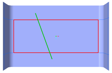
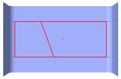
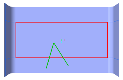
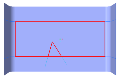
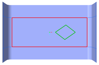
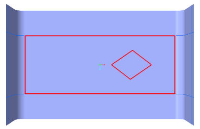
The splicing curve defines the splicing or darting trajectory. It can be an open chain or a closed chain, but it must form a closed loop with itself or with the ply boundary. The following examples show various ways you can select a splicing curve to splice or dart plies.
Some splicing curves and their splicing results are as follows:
|
Splicing Curve
|
Splicing Result
|
|---|---|
 |
 |
 |
 |
 |
 |
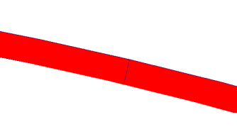
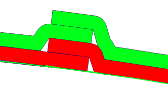
The overlap settings define how plies created as the result of splicing the original ply are connected.
• Butt Connection—The plies created as the result of splicing the original ply touch each other but do not overlap.
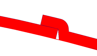
• Overlap Connection—The plies created as the result of splicing the original ply overlap.
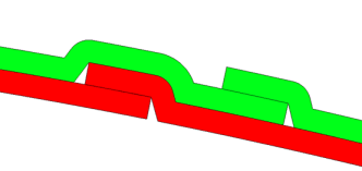
The stagger settings define how plies are staggered when you splice two or more plies.
• No Stagger—The plies created as the result of splicing the original ply are not staggered.
• With Stagger—The plies created as the result of splicing the original ply are staggered.
Overlap and stagger should be in the same direction. For this, the values of both the overlap offset and the stagger offset must be negative, positive, or 0. |
Splice or dart plies as follows:
1. Click  Splice Plies. The Splice Plies tab opens.
Splice Plies. The Splice Plies tab opens.2. Click in the Plies to Splice box and select the plies to splice or dart.
3. Click in the Splicing curve box and select a curve from the graphics window to defines the splicing or darting trajectory.
4. To set overlap and stagger settings follow the steps below:
a. To enable overlapping of plies, click  Overlap and type or select a value for the overlapping offset.
Overlap and type or select a value for the overlapping offset.b. To enable staggering of plies, click  Stagger and type or select a value for the staggering offset.
Stagger and type or select a value for the staggering offset.c. To toggle the direction of both the overlap offset and the stagger offset, click  Flip Splicing Direction.
Flip Splicing Direction.5. Click  OK.
OK.
OK.The new plies that are created after splicing the original ply inherit the properties of the original ply. They are placed under a header that represents the original ply. You can use the header to change the properties of the new plies.