Draping Simulation
About Draping
A composite ply requires deformation to conform it to a non-gaussian and doubly curved surface. Creo uses a kinematic draping algorithm to model the shear deformation required in a ply to allow it to conform to the required shape. Shear deformations in the ply helps understand ply producibility. The algorithm also generates ply flat pattern. The ply flat pattern provides the ply shape in a flattened state which is useful for physically cutting the ply fabric.
The kinematic draping model requires initial constraints to identify a unique solution for a given case. The initial constraints are a seed point and two directions that represent one warp fiber and one weft fiber, both must pass through the seed point.
The seed point is the first point of contact between the ply and the mold or the underlying ply. The fixed warp fiber and the fixed weft fibers pass through the seed point. The direction of the fixed warp fiber is defined in reference to the ply roll direction. This direction specifies the draping direction. The direction of fixed weft fiber is at 90° to the direction of fixed warp fiber.
|
|
Although it is best practice to align the fixed warp and fixed weft fiber directions to the directions of the physical fibers, they do not necessarily need to be aligned.
|
You can change the draping direction by applying a draping angle offset to the ply roll direction. The fixed warp and the fixed weft fibers of the fishnet provide the direction to smooth the ply. They divide the ply logically into four quadrants. Each of these quadrants is draped independently.
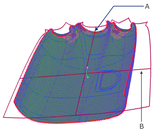
• A—Fixed Warp Fiber
• B—Fixed Weft Fiber
The process of modeling kinematic draping of a ply involves the calculation of the locations of drape points and generation of a fishnet. Drape points are the crossover points of warp and weft fibers. They must lie on the surface of the mold or the underlying ply to be draped. The fishnet is a net of drape points. It is possible to determine the location of a drape point if and only if the locations of the adjacent drape points in the weft and the warp direction are known or the locations of two preceding drape points in the warp or the weft directions are known. Since the fibers are inextensible, the distance between adjacent drape points is constant, this is called the step length. Creo provides the flexibility to adjust the step length.
Draping Results
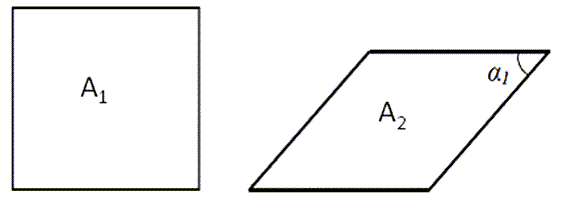
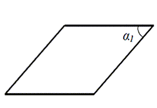
Shear—Shows the in-plane shear deformations when a flat ply conforms to the required shape during draping. The ability of a ply to shear depends on the micro-mechanical arrangement of the ply which is defined by warn and limit angles. The shear angle in the following figure is 90°-α1.
Longitudinal and Transverse Orientations—Shows the predicted true orientations in the longitudinal and transverse directions when the ply undergoes deformations. Due to the global rotation of the fishnet element, these orientations are related to, but not the same as, the shear angle.
Draped Ply Thickness—Shows the results of ply thickness multiplied by the ratio of area of the sheared fishnet element to the area of the not deformed square element. The difference in laminate properties caused because of the change in thickness is generally insignificant when compared to the deviation in fiber angle for realistic shear deformations. Therefore, it is not often considered in downstream analysis. The following figure shows an example of change in ply shape due to shear deformations.