Create a Core Ply
A core ply is a thick ply made up of materials such as foam, paper, aluminum, or honeycomb structure.
A core ply is defined by boundary, rosette, material, orientation, drop-off, name, sequence, and taper. To create a core ply, you must first set up the Composite Design environment. To learn how to setup the Composite Design environment, see Setting Up the Composite Design Environment.
When you create a core ply, a core ply feature is created in the Composite Tree and a core object is created in the Laminate Tree.
|
|
You can change the default prefixes of the name and the sequence of a laminate object in one of the following ways:
• Click > . In the Creo Parametric Options dialog box, click > . Specify the values under Name Policy Settings.
• Set the Configuration Options: Name Policy Settings.
|
Create a core ply as follows:
1. Click  Core Ply. The Core Ply tab opens.
Core Ply. The Core Ply tab opens.2. In the Boundary chains collector, select chains to define the boundary of a ply. You can define a boundary by selecting a single closed loop, one outer and one or more inner loops, multiple individual loops, or multiple intersecting curves, edges, or loops. Make sure that the ply boundary does not overlap the layup surface boundary. To learn how to define the boundary of a ply, see Example: Define a Ply Boundary.
To invert the selection, click Flip Side. |
3. To change the default rosette, click in the Rosette box and select a rosette from the Composite Tree.
4. To change the default material, select a different composite material from the Material list.
5. In the Orientation box, select or type an angle to set the orientation of the ply relative to the X-axis of the rosette.
6. (Optional) In the Core Settings tab, change the following settings:
◦ In the Drop-off box, select Default or specify a value. When you select Default, the core ply will use the drop-off value defined in the setup. When you specify a custom value, that value will be used.
◦ In the Name box, specify a name.
◦ In the Sequence box, specify a sequence. Two or more laminate objects can have the same sequence.
7. In the Taper tab, do the following:
a. In the Sets box, select a taper set or click New set to define a new taper set.
b. In the Taper chains box, select a chain to apply the taper. The chain must be a subset of the boundary that is selected for the core ply, as shown in next the figure.
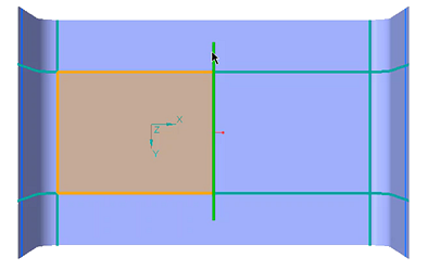
You can also create multiple tapers, one taper on each tangent chain. For example, you can create four different tapers in a rectangular boundary. However, when you create a fillet at one corner, the edges connecting the fillet are considered as a single tangent chain, and you can create only three tapers. |
c. Specify the values for D1 and D2.
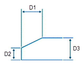
D1—Horizontal taper dimension
D2—Vertical taper dimension
D3—Cured thickness of the composite material
D3 is a read only value and it is displayed only for reference. |
8. Click  OK.
OK.
OK.Right-click a core ply feature and select  to locate its core object. to locate its core object. |