Example: Define a Ply Boundary
When you create a manual ply feature or a core ply feature, you can select a closed a loop and define the boundary of the ply in a variety of ways. Some of the examples are as follows:
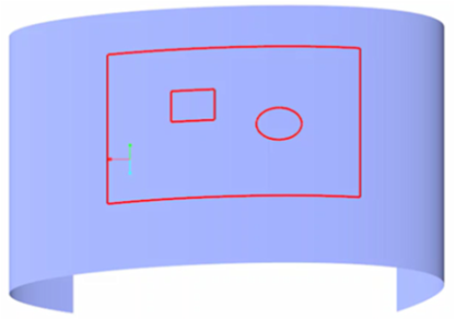
Define a boundary by selecting a single closed loop
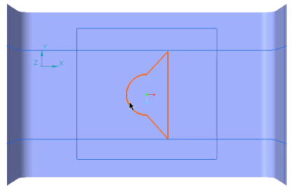
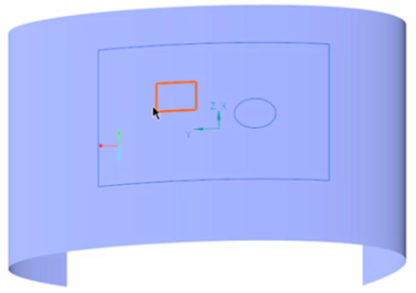
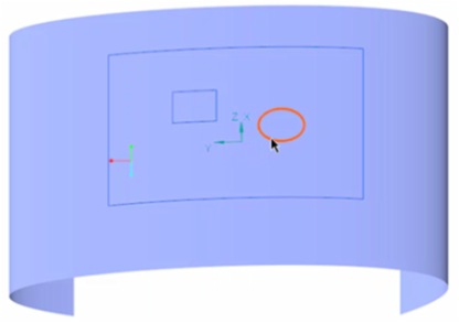
1. Move the cursor over the layup surface to find a single closed loop.
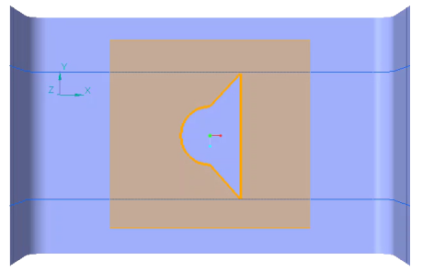
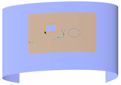
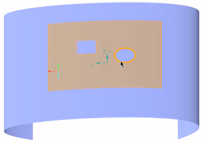
2. Select the single closed loop as the boundary for the ply.
Define a boundary by selecting one outer and one inner loop
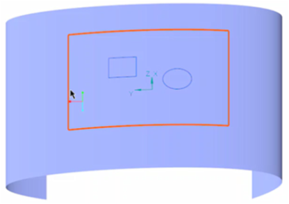
1. Select the outer loop.
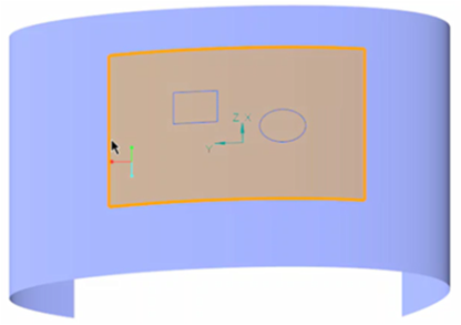
2. Click Add Loop and select the inner loop.
The resulting boundary is shown in the next figure.
Define a boundary by selecting multiple loops
1. Select the first loop.
The resulting boundary is shown in the next figure.
2. Click Add Loop and select the second loop.
The resulting boundary is shown in next figure.
3. Click Add Loop and select the third loop.
The resulting boundary is shown in next figure.
4. A ply created with the resulting boundary is shown in the next figure.
Following the same approach, you can add multiple loops to select the boundary of a ply or a core.
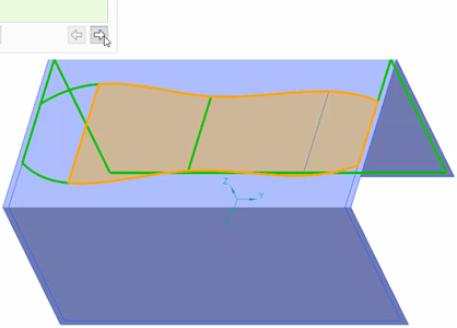
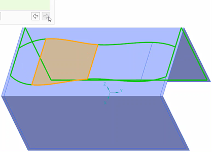
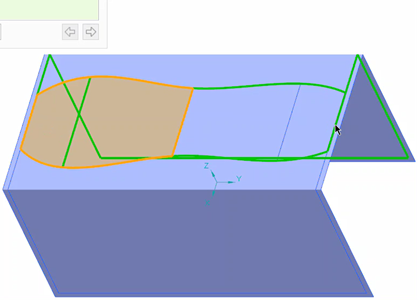
Define a boundary by selecting multiple intersecting curves, edges, or loops
1. Press and hold CTRL while selecting multiple edges, curves, or loops. The next figure shows an example of such selection.
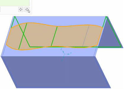
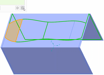
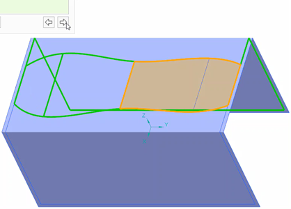
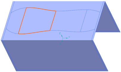
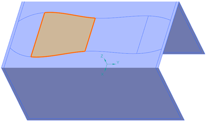
2. Use  or
or  to select a boundary from the available solutions shown in the next figures.
or to select a boundary from the available solutions shown in the next figures.