
Creating the Machine
Now we will build the 5-Axis LaserDyne Machine that will simulate the Cutter Location (NCL) toolpath from the previous page.
1. Open ![]() the LASERDYNE_5AX.ASM assembly.
the LASERDYNE_5AX.ASM assembly.
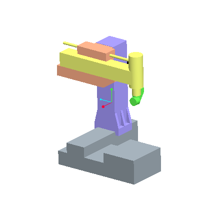
In this case, the X,Y,Z and C Axes are already defined as parts with mechanism constraints. We need to define the D Axis that will hold the tool.
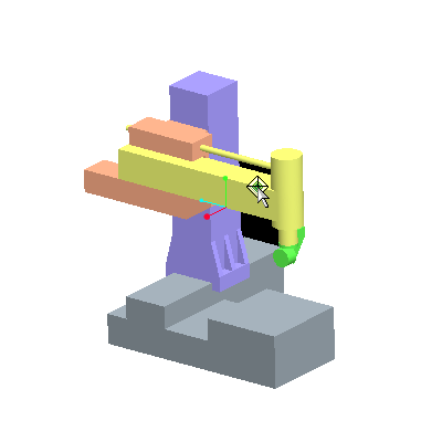
2. Move the machine as a regular mechanism by using the Drag Packaged Components tool ![]() .
.
3. Pick anywhere on the yellow (yaxis.prt) part, then drag around with mouse. Close the Drag dialog box when done.
4. Select Add Component ![]() and assemble daxis.prt.
and assemble daxis.prt.
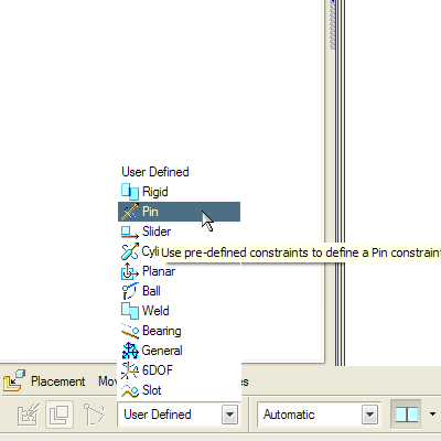
5. Change the constraint type from User Defined to Pin ![]() .
.
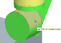
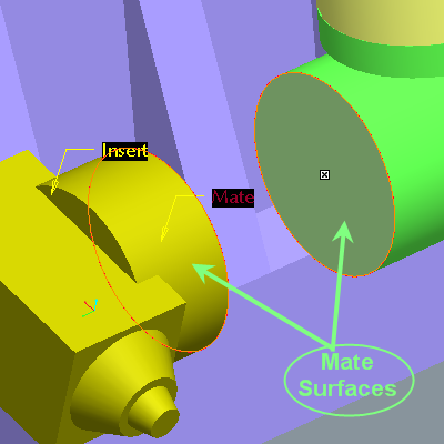
6. Select the cylindrical surface from both the caxis part and daxis part as shown.
7. Select the 2 planar surfaces for a Mate. Ensure the Mate is Coincident by selecting the Position Coincident ![]() icon from the Position drop down list in the dashboard.
icon from the Position drop down list in the dashboard.
8. Click ![]() on the dashboard to finish the operation.
on the dashboard to finish the operation.
The machine is complete! Feel free to move it using the Drag Packaged Components tool ![]() from the main toolbar.
from the main toolbar.