Task 3. Create, move, and manipulate drawing details
|
|
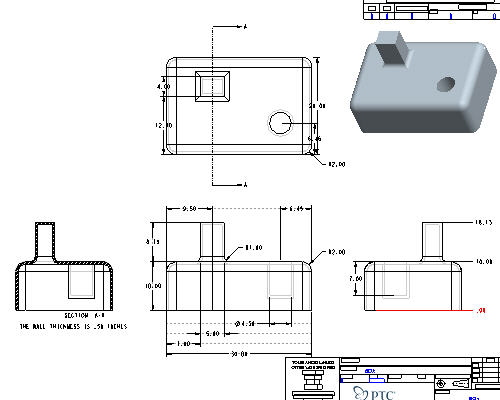
Most of the work done when creating drawings involves detailing. When you see the model dimensions on the drawing courtesy of the drawing template, many times you will need to move them around, clean them up and even delete existing or create new dimensions. |
-
Zoom-In
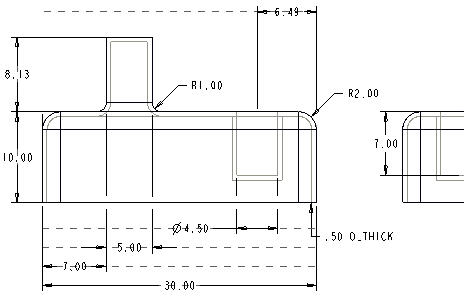
 to the FRONT and RIGHT views as shown (Click the Right Mouse Button to cancel the zoom function).
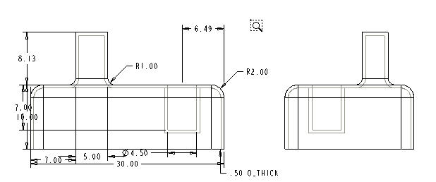

Following any zoom action, always click the Right Mouse Button (or choose Select Items
 ) before selecting a dimension, view, drawing note, etc.. . This cancels the zoom function and returns to the selection cursor.
 -
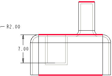
Select the vertical 7.00 dimension on the front view (it will highlight in red).
-
Hold down the Right Mouse Button and choose Move Item to View.
-
Select the RIGHT view to move the dimension to the Right view.

-
Select the vertical height dimension of 10.00.
With a dimension selected, the cursor changes shape to indicate what motion will be performed by holding down the Left Mouse Button and dragging:
 for Up, Down, Left and Right movement;
  for Up and Down movement; and
  for Left and Right movement.
 -
Hold down the Left Mouse Button and drag 10.00 dimension farther away from or towards the geometry.
-
Select and drag the 10.00 dimension up and down (notice the center snapping).

Center Gravity: Dimensions are automatically centered between the witness lines and when dimensions are moved, they snap to this centered location. This "gravity" location aids in placement.
-
With the 10.00 unit dimension still highlighted, press and hold the Right Mouse Button and select Flip Arrows from the pull down to change the direction of the arrows.
-
Repeat the Flip Arrows command to switch the arrows back.
-
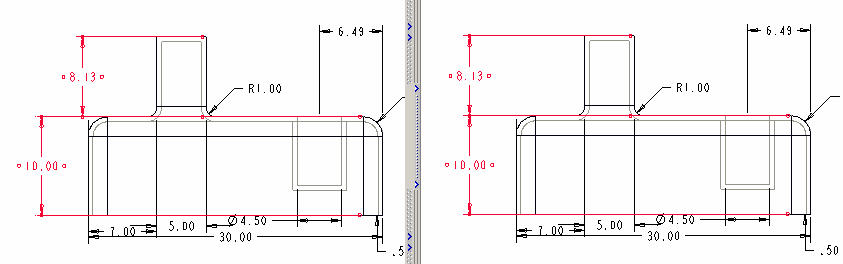
With the 10.00 unit dimension still highlighted, hold down the CTRL key and select the 8.13 dimension (the height of the protrusion).

Multi-select items by holding down the CTRL key and selecting the items.
-
Press and hold Right Mouse Button and select Align Dimensions from the pull down.
-
Select the FRONT view.
-
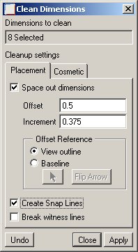
Press and hold Right Mouse button and select Cleanup Dimensions from the pull down. A dialog box will pop-up similar to the figure below.
-
Choose the options and type in the values as shown in the figure above.
-
Click Apply and Close. Notice how this view can be quickly cleaned up.
To use this technique on multiple views, by first multi-selecting the views and then doing a Cleanup Dimensions to drastically reduce the amount of manual effort normally involved.
-
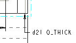
Select Info from the pull down menu at the top of the window and choose
 Switch Dims. This shows the symbol, or "parameter", for the dimensions.
Repeating
Switch Dims will toggle the display of dimensions back and forth from numeric to symbolic. Every dimension (and its tolerance values) are represented inside Pro/ENGINNER by these symbols that can be used in relations or in parametric notes.
Now let's add a parametric note that calls-out the wall thickness.
-
Select Insert -> Note... from the drop-down menus.
-
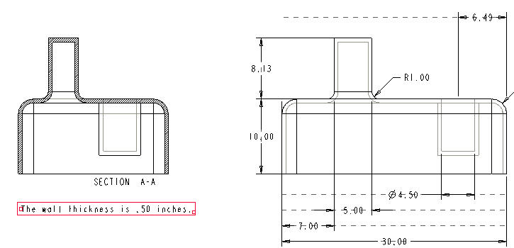
Select Make Note from the menu manager and accept all the defaults.
-
Click a spot anywhere under the Left cross-section view as the desired note location and middle-click
-
Type THE WALL THICKNESS IS &D21 INCHES and click Accept
 or press Enter.
This symbolic name may be different than shown above. If so ensure you enter in the correct symbolic name in the note creation box.
-
Select Accept
again as you are not creating another sentence. -
Click Done/Return from the menu manager.
You can also add Ordinate Dimensions that use a single witness line with no leader, and are associated with a baseline reference. They are used mostly for flat plate or sheetmetal designs but we will illustrate an example of this capability on our box part.
-
Insert, Dimension, Ordinate... from the drop-down menus.
-
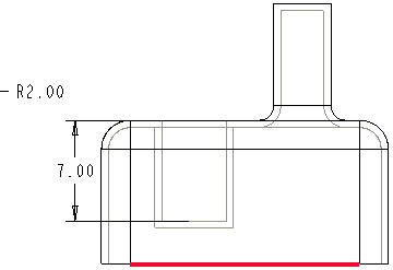
Select the bottom edge as a baseline from the Right view as shown in the figure below.
-
Select the two edges as shown below to create ordinate dimensions.
-
Place the cursor to the right of the view and click the Middle Mouse Button to place the dimensions.

-
Click Return from the menu manager.
You can convert linear dimensions to ordinate dimensions and vice-versa. You can also have ordinate dimensions automatically created under Insert -> Dimension -> Auto Ordinate... as opposed to picking the individual entities in our exercise. This is extremely invaluable for flat plate and sheetmetal parts.
-
Click Save
 from the main toolbar.
 -
Click OK.
-
 Refit the whole drawing in the window.
Congratulations! You have successfully created your first part drawing.