Task 2. Create, move, and manipulate drawing views
-
Select the FRONT view so that it is outlined with a dashed red box. Make sure that you don't accidentally pre-highlight a dimension or dimension witness line and select that item. If you do, just re-pick on the view to select it.
-
Press and hold the Right Mouse Button over the view and uncheck Lock View Movement.
-
With the FRONT view still selected, Press and Hold the Left Mouse Button and drag the view outline around.
-
Release the Mouse Button to place the view.

Notice the intelligence of the other views as they will continue to line up and follow the FRONT view accordingly.
-
Return the FRONT view to its original position by using Edit > Undo from the menus (or use CTRL-Z)

Let add a projected view based off the Front view
-
Select the FRONT view again,
-
Press and hold the right mouse button and select Insert Projection View...
-
Move the mouse around and notice that you have 4 possible projection options.
-
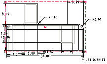
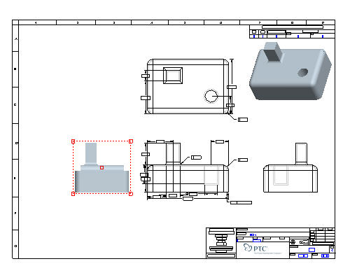
Select a point to the left of the FRONT view. The view will look similar to the figure below.
-
With the new view still selected, press and hold the right mouse button and select Properties.

To change the properties on more than one view at a time, hold down the CTRL key while selecting them and then access the Properties window from the right mouse button menu. This can include determining visible areas, scaling, defining cross-sections, showing the model in various states, and aligning and setting the view origins.
-
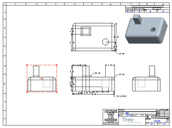
Select the View Display Category in the Drawing view dialog box , change the Display Style from Follow Environment to Hidden.
Follow EnvironmentUses the setting from Tools > Environment > Display Style or one of the view display style icons (
 Wireframe,
  Hidden Line,
  No Hidden,
  Shaded) in the Pro/ENGINEER graphics window.
-
Click Apply from the Drawing View dialog box. The view will appear similar to the figure below. (Move the Drawing View dialog box if necessary to see the changes)
Create a cross-section of the new view we just created
-
Select the Sections category in the Drawing View dialog box.
-
Choose 2-D cross section, and click Add Section
 .
. -
Select section A (which is pre-defined in the part) from the Name drop-down.
-
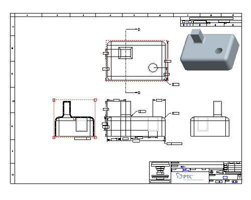
Click Apply.

You can also modify the cross-hatching for certain materials or preferences.
-
Scroll the section definition window all the way to the right.
-
Click on the empty "Arrow Display" box to activate it.
-
Select the TOP VIEW from the drawing window.

-
Click OK.
Cross-section and view arrows can also be added by selecting the view and choosing Insert, Arrows... from the drop-down menus (or by using the right mouse button menu to choose Add Arrows)
|
|
Let's look at how we can manipulate the views and create additional ones as needed. |