Task 1. Create a New Part Drawing
-
Start Pro/ENGINEER Wildfire 4.0 Schools Edition if necessary.
-
If Pro/ENGINEER is already running, close all windows then remove all objects from session using File > Erase > Not Displayed...
-
File > Set Working Directory..., browse to \HANDS-ON_WF4\04-DRAWING
(or in the Navigator Folder Browser , browse to the specified folder, then Right click on it and select Set Working Directory.)
 -
Click the New
 icon on the main toolbar and select Drawing as the Type in the New Object dialog box.
 -
In the New dialog box, type BOX as the Name.
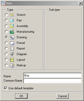

Note that the Use Default Template option is enabled.
-
Click OK from the New dialog box.
-
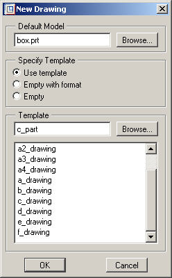
Click Browse from the New Drawing dialog box and select BOX.PRT as the Default Model.
-
Click Open.
-
Under Specify Template, select the radio button Use template.
-
Under the Template section, click Browse and select C_PART.DRW.
-
Click Open.

Drawing templates may be referenced when creating a new drawing. They automatically create the views, set the desired view display, create snap lines, and show model dimensions based on the template.
-
Click OK from the New Drawing dialog box. The template drawing will automatically layout the drawing.
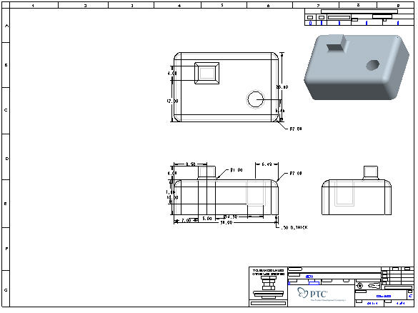

The use of drawing templates can save an enormous amount of time by automatically laying out your standard view with dimensions, cross-sections, notes, etc.
To make drawing creation even easier, drawing templates can be used to automatically create a new drawing for each new part and assembly you create, thus saving you the need to do what you just did here.
-
Click the Datum Planes
 , Datum Points
  , and Coordinate Systems
  icons in Pro/ENGINEER's main toolbar.
 These buttons toggle datum planes, axes, points and coordinate systems on and off so that your graphics window doesn't become too cluttered.
-
Zoom in
 on the title block in the lower right corner of the drawing.
Take note of the intelligence built into the format. Not only has the drawing name, scale and date been filled in, but these values are linked back to the source model and will change if changed in the model -- this insures complete accuracy of the information displayed.
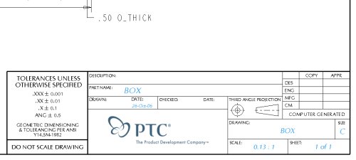
Also note the embedded jpeg logo image. You can use the OLE (Object-Linking Embedding) capabilities for inserting images and other file types into your drawings.
-
 Refit the whole drawing in the window.
Take note of the shaded isometric view in the upper right corner. Using shaded views in drawings gives more options for communicating critical design information since colors can provide visual cues to help describe designs. By using shading, drawings can include more detail.