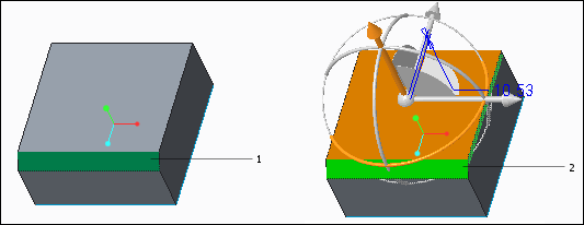
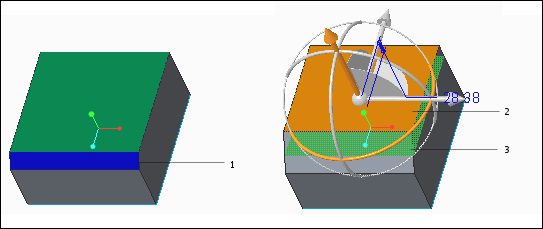
When performing operations on selected surfaces, you can ignore or consider adjacent round or chamfer geometry. If you ignore the round or chamfer geometry, use the  Not Chamfers or the
  Not Rounds option to treat rounds and chamfers as surfaces. As a result, the round or chamfer geometry is removed and operations are performed only on the selected surfaces. When you choose to consider rounds or chamfers, use the Recognize Chamfers or Recognize Rounds option. Here, the round or chamfer geometry is recreated and operations are performed taking into consideration the selected surface, rounds, and chamfers.
Not Chamfers or the Not Rounds option to treat rounds and chamfers as surfaces. As a result, the round or chamfer geometry is removed and operations are performed only on the selected surfaces. When you choose to consider rounds or chamfers, use the Recognize Chamfers or Recognize Rounds option. Here, the round or chamfer geometry is recreated and operations are performed taking into consideration the selected surface, rounds, and chamfers.