You can change the display properties for a viewport, including color, perspective, and clipping plane settings. You can also print a viewport's contents from this dialog. These properties only affect the current viewport.
To change a viewport's properties,
1. Right-click a viewport and click Viewport Properties.
2. Set the following options:
◦ Light: Opens the Light dialog, where you can change the settings for all the active lights.
◦ Background: Opens the Viewport Background dialog, where you can change the color(s) or background image for the current viewport. For more information, see
Change the background of a viewport.
◦ Axes: Turns the axes reference display on or off. You can also press the F3 key to toggle this display on and off.
◦ Frozen: Locks the contents of the viewport so it cannot be moved or rotated. If you have more than one workplane, the active workplane is frozen. Any objects you create are added to the frozen viewport's drawlist. However, they are not added to the view until you unfreeze the viewport.
◦ Projection: Objects are drawn with a visual indication of depth, as illustrated in the image below. Select Parallel (no perspective) or Perspective. Click Options to change the perspective viewing options such as field of view and depth of field.
◦ Direction: Sets the X, Y, and Z directions in the viewport. Select one of the following:
▪ Active WP to set the direction based on the active workplane.
▪ WP to select any workplane in the viewport. The direction will be changed to match the workplane.
▪ General to select an object in the viewport with the 3D CoPilot. The direction will be changed to match the CoPilot's feedback arrows.
◦ Clip Planes: Check Camera, and you can enter coordinates for the Front and Back locations. Enabling Camera clipping automatically deactivates any active clipping feature.
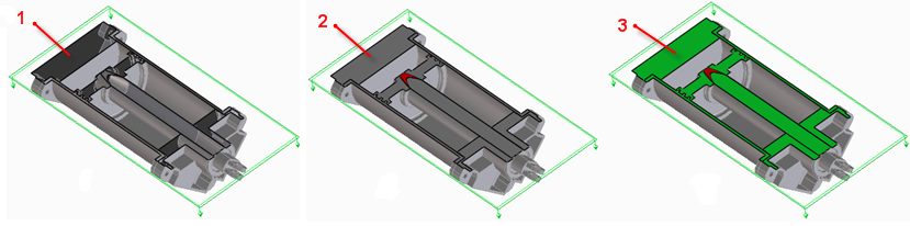
◦ Visual Cap: Visual capping makes clipping planes more visible by changing the color of parts along the clipping plane. When Visual Cap is enabled, you can select the color: Part Color or Cap Color (green by default).
The following images display the models without the hatch lines on the clipping plane. For more information about removing the hatch lines, see
Clip Hatches.
1. No visual cap
2. Part Color cap
3. Cap Color cap
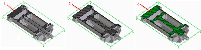
The following images display the models with the hatch lines on the clipping plane.
1. No visual cap
2. Part Color cap
3. Cap Color cap
◦ Visual Interference: Visual interference is only available on system that support OpenGL. The visual interference check is applied to all parts in the viewport. Any overlap between parts in the viewport's drawlist is detected and highlighted in red, as shown in the image below. This option must be used with Visual Cap on, and is only visible when you are clipping.
3. To print the viewport, click Dump or HR Print to print the contents of a viewport to a printer or an image file.
4. To change the default background color, click Settings in the Defaults section.
5. Click OK to complete the operation. Changes are applied as you change settings.
 to complete the operation. Changes are applied as you change settings.