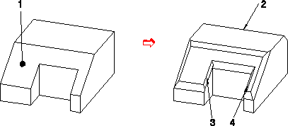
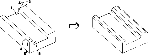
1. Click Modeling and then, in the Engineering group, click the arrow next to  Chamfer.
 Chamfer.
 Chamfer.
 Modify. The Modify Chamfer dialog box opens.
• Select a chamfer in the viewport and click  on the Command Mini Toolbar (CMT) to modify that chamfer. on the Command Mini Toolbar (CMT) to modify that chamfer.• While modifying a chamfer, drag the CoPilot arrows, press the SPACEBAR, and select Distance on the Option Mini Toolbar (OMT). The options available on the OMT depend on the selected element. |
• Click Propagate to propagate the change in a chamfer distance to subsequently-selected chamfer if possible. For example, if you change the distance of a chamfer from 8 to 12 and then select other chamfers, the distances of other selected chamfers also change to 12. • Click Restore to restore the distance of the chamfer to the value before the currently-active selection. Old Chamfer Definition shows the value of the distance of the chamfer before the active selection. • Click Clear active selection to deselect the selected chamfers. |
• Click Preview to preview the model with chamfers. • You can click either Realistic or Quick to see either realistic feedback or quick feedback when you chamfer an edge in the viewport. See
Realistic feedback. |
 to complete the operation.
