A cutaway area is a local section of an existing view. You define a region to cut, and then specify the depth to cut to, that is, the section plane. Creo Elements/Direct Annotation displays the sectioned or cut area of the part on the view, labeled and enclosed within the original border. A cutaway border is defined in the same way as a detail border.
You can remove a cutaway area on a view with the Remove Cutaway command.
To create a cutaway,
1. Click Annotation and then, in the Setup group, click the arrow next to Dep View.
2. Click Cutaway. The Cutaway dialog opens.
3. Click Cut Secured Parts to create a cutaway through secured parts.
4. Click Real View on Parent if you wish to display a 3D preview of the model used as input for the cutaway operation. A real preview is especially useful for cutaways in dependent views (for example, section or detail views).
5. Specify the parent view in one of the following ways:
◦ Type the name and path of the view in the Parent View box.
◦ Click the view in the Creo Elements/Direct Annotation Viewport.
◦ Select the view from the Drawing Browser.
6. Click one of the border types:
◦ Rectangle
◦ Circle
◦ Polygon
◦ Spline (You can define the default border type in Default Setting Browser.)
7. Click the first point of the border.
8. Complete the border:
◦ For rectangles and circles, click the other point to define the border.
◦ For polygons and splines, continue clicking points as required. You can click Back to undo the last specified point of the border. When you are finished, click Accept.
To avoid problems, define borders as shown in the image in blue. Avoid following part borders (shown in red).
9. If necessary, enter a new cutaway number in the Number data entry field.
10. Specify the border depth, click Depth, the menu expands and the 3D VP window opens. Specify one of the following options:
◦ by Point sets the depth of the cutaway to a selected point on the part. The 3D VP window helps you to specify an exact point on the part.
◦ by Face sets the depth of the cutaway to a selected face on the part. The selected face must be planar, and parallel to the plane of the cutaway border.
◦ by WP sets the depth of the cutaway to a selected workplane. The workplane must be parallel to the plane of the cutaway border. You can either select the workplane in the 3D VP window, type its name in the box, or select it in the Structure Browser.
11. Click to complete the operation.
Sectioned areas will be displayed with hatching.
The following options affect the contents of the cutaway and its parent view:
• Visible Border — The cutaway border is displayed in the view.
• Cut Secured Parts — Also secured parts are cut
You now have to update the original view to see the cutaway area. Sectioned areas will be displayed with hatching.
It is possible to define a default 3D viewport as reference for drawlist and view direction.
To remove a cutaway,
You can remove a cutaway area on a view with the Remove Cutaway command. The parent view is restored to its original state after an update operation.
To remove a cutaway,
1. Click Annotation and then, in the Setup group, click the arrow next to Dep View.
2. Click Remove Cutaway.
3. Click the border of the cutaway in the Creo Elements/Direct Annotation Viewport.
Creo Elements/Direct Annotation asks you for confirmation.
4. Click Yes in the Question box.
You now have to update the original view of large a assembly to see it without the cutaway information.
 Dep View.
 Cutaway. The Cutaway dialog opens.
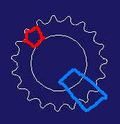
 to complete the operation.
 Remove Cutaway.