You can set or change the attributes of values, tolerances, formats, fix texts, text properties, and arrow and line properties in the Dimension Properties dialog box.
To modify dimension properties,
1. Click Annotation and then, in the Annotate group, click the arrow next to Properties.
2. Click Dimension.
3. Select one or more dimensions to modify its properties.
You can also preselect dimensions in the viewport, right-click and choose Dimension Properties from the context menu. The Dimension Properties dialog box opens.
With the dialog box open, you can select different dimensions to display and modify at any time. You can also select Default from the specific property to reset most properties to the default.
At the top of the dialog box, the Dimensions field displays the types of dimensions that were selected and the number of each type.
4. The Value pane includes the following settings for both Main and Second dimension values:
◦ In the Values section:
▪ Value: Thread dimension properties are shown as keywords. You can change the keyword (a user-specified keyword is indicated by [mod] next to the Value label), and you can reset it by selecting Reset from the list. If you select multiple dimensions with different keywords, Creo Elements/Direct Annotation displays Various in the Value box.
▪ Length Unit and Angle Unit: Change the units in which the dimension value is measured.
▪ Bracket: Surround the dimension value with brackets.
▪ Underline: Display modified values underlined.
◦ In the Dimension Orientation section:
▪ You can set the orientation of the dimension value. Creo Elements/Direct Annotation prompts you to select a reference line if you select Parallel To or Perpend To, and to type an angle if you choose Inclined.
5. The Tolerance pane includes the following settings:
◦ Type: You can set, remove, or change a dimension tolerance type. Creo Elements/Direct Annotation retains the tolerance values if possible; otherwise, it assigns default values.
◦ Upper and Lower: Set the limits, depending on the type of tolerance. For Plus/Minus tolerances, Creo Elements/Direct Annotation uses only the Upper value. For Limit tolerances, the maximum and minimum dimension values are displayed.
◦ Basic: Set a basic (zero) tolerance.
6. The Format pane includes the following settings for both Main and Second dimension values:
◦ In the Precision section:
▪ Nominal: Select the decimal positions from the list for the dimension value.
▪ Tolerance: Select As Nominal, or specify the decimal positions from the list for the tolerance value.
◦ In the Format section:
▪ Scope: You can specify that the changes in the dialog below apply to both the value and tolerance by specifying Main Dim, or you can limit the changes by specifying Main Value or Main Tolerance. The same is true for the second dimension.
▪ Zero Suppression, Sign, and Punctuation: Select a value from the list.
7. The Fix Text pane includes the boxes for Prefix, Basic (for Prefix), Subfix, Postfix, Basic (for Postfix), and Superfix. Thread dimension properties are shown as keywords in the Prefix and Postfix boxes. You can set, change, or delete the keywords. Press the Enter key to complete your text. The lists contain up to 20 entries that have been made at some time; the oldest ones fall off the list when you have entered more than 20. Click Prefix, Postfix, Subfix, or Superfix to open a text editor if you wish to create longer text or include special characters.
Basic (for Prefix) and Basic (for Postfix) are available only if you select a basic tolerance.
8. The Text Props pane includes the following settings:
◦ In the upper half of the dialog box, the properties apply to the whole dimension. Most of these settings are intuitive, but it may be helpful to know:
▪ Gap: Define the size of the space between the dimension text and dimension line.
▪ Space: Define the space between the dimension text and the dimension line when the location is set to Above or Below.
◦ The Scope determines what attributes of the dimension will be affected by changes in the lower half of the dialog.
To use the same dimension text color for dimension lines, click the Connected To Line check box (default) near the Color box. If you change the color of dimension texts subsequently, similar color is also used for dimension lines.
To use separate colors for dimension texts and dimension lines, clear the Connected To Line check box.
9. The Arrow/Line pane includes the following settings:
◦ In the upper part of the dialog box, the Type, Fill, Abs Size, Rel Size, and Placement settings for First and Second arrows.
◦ In the lower half of the dialog,
▪ In the Extension Line Offsets section, you can specify the offset of the extension line from the referenced geometry and from the dimension line.
▪ In the Lines and Arrows section, you can specify color and pen size.
To use the same dimension line color for dimension texts, click the Connected To Text check box (default). If you change the color of dimension lines subsequently, similar color is also used for dimension texts.
To use separate colors for dimension lines and dimension texts, clear the Connected To Text check box.
You cannot change the direction of arrows for broken dimension lines.
10. The Indicator pane includes the following settings, that depend on the type of tolerance:
◦ For None, Basic, and Plus/Minus tolerances, the type, symbol, and datum of the first and second indicators for the dimension.
• The fields under Indicator 2 are not available for these tolerances.
• Under Indicator 1, the fields for the second indicator are available only after you have defined all the fields for the first indicator.
The following table shows examples of indicators for each type of tolerance:
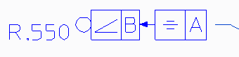
None
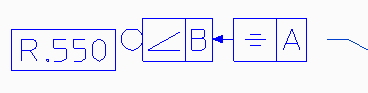
Basic
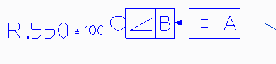
Plus/Minus
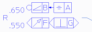
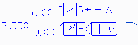
◦ For Limit and Upper/Lower tolerances, the type, symbol, and datum of the first and second indicators for the upper and lower values. The fields under Indicator 1 define the upper value and the fields under Indicator 2 define the lower value, respectively.
Under Indicator 1 and Indicator 2, the fields for the second indicator are available only after you have defined all the fields for the first indicator.
The following table shows examples of indicators for each type of tolerance:
Limit
Upper/Lower
For proper alignment, in the Text Props pane, set Scope to All Tolerances (Main, Second) and Rel Size to 1.
11. At the bottom of all tabs:
◦ Click Set to Default to select a style to copy to the dimension.
◦ Click Copy from to copy dimension properties from another dimension to the current dimension.
◦ Click Copy to to copy the current dimension's properties to another dimension.
Under Properties to copy select which properties to copy to the dimension. (The check boxes correspond to the tabs in the Dimension Properties dialog box.)
To copy the indicator properties, select the All Fix Texts check box.
 Properties.