Concurrent state (dictionary item)

For automation interface information about a Concurrent State, see
Comment (automation interface). For automation interface purposes, a Concurrent State is a State that has its UML State Type set to Concurrent.
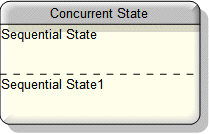
A Concurrent State is partitioned into regions, which are separated by a dashed line. Each region represents a Concurrent Substate into which you can add States. By default, a Concurrent State is created with two concurrent substates.
Concurrency modeling is used to simplify state models, where there are separate areas of concern. This is done by splitting a Concurrent State into partitions. It should not be confused with parallel execution, described as tasks on the concurrency diagram. The separate substates in the concurrent partitions can change state independently. It is this independence of action that the concurrent states are used to represent. Entry States and Exit States are used to describe explicit synchronization between the separate Substates. Any Change of state to enter or exit from a concurrent State impacts the Substates in all concurrent partitions.
Create a Concurrent State through a Modeler explorer pane or a State Diagram:
• In a Modeler pane, right-click a State Machine or Sequential State, and select > .
• On a State Diagram, click the  Concurrent State button, and then click the diagram background (within the frame) or within a Sequential State.
 Concurrent State button, and then click the diagram background (within the frame) or within a Sequential State.
On a Concurrent State you can create doActivities that are continuous performed by the Concurrent State. A doActivity terminates when the Concurrent State is complete, or when the Concurrent State is exited. A doActivity can be an Activity, Operation or State Machine.
When used on a State Diagram, a Concurrent State's notation is as follows.

The View Options on a State Diagram allow you to show or hide the Name, Event Action Blocks, Do Activities and Compartment Names. By default, all the preceding properties are shown. The view options are set through the Composite State entry. See
Composite state view options - state diagram.
On a State Diagram, you can populate Concurrent States: right-click the State Machine (frame) or Sequential State that owns the Concurrent States, and select > . Note that all owned Concurrent, Atomic, Sequential and Submachine States are added to the diagram.
You can change a Concurrent State into an Atomic State or Sequential State: On the Concurrent State's Property Pages, click the State Type tab, and then select the required type. When you change a Sequential State to an Atomic State, Modeler creates a child State Diagram.
In the Dictionary pane, Concurrent States are listed in the UML\States folder.
The following sections provide information about how a Concurrent State is used in the model.
Properties
In addition to the standard properties a Concurrent State has these properties:
•
State Type (UML State Type through the automation interface)
Owned by
 Atomic State (through child State Diagram)
Owns
 Dependency —The Dependency is owned jointly by the Concurrent State and the other associated item. The access permissions you have to a Dependency are determined by the access permissions of the dependent item.
 Transition —The Transition is owned jointly by the Concurrent State and the other associated item. The access permissions you have to a Transition are determined by the access permissions of the source item.
Defined in these parts of the model
Shown on these diagrams
Can be linked to these dictionary items
In addition to the owning State Machine or Sequential State, a Concurrent State can be linked to the following items.
 Stereotype —To make a Concurrent State valid for a Stereotype, make State a valid item type.
 on the Concurrent State's icon indicates that the item is a
 Sequential State
 State Machine
 Comment
 Constraint
 Event Action Block
 State Model
 State Diagram
 Variant Diagram