For information about showing compartments on diagram symbols, setting up default view options and adding existing elements to the diagram, see the following topics:
For information about the creation and appearance of elements that can be shown on all Product diagrams (Alias, Definition, Information, Metadata, Overlap and Same As elements), click here
.
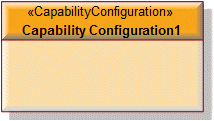
When you create an SV-2 Resource Communications Description from a Capability Configuration, Modeler does not add the owning Capability Configuration to the diagram.
To show the owning Capability Configuration on the diagram: right-click the background of the diagram, point to Populate, and then click Owner.
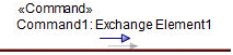
• Click the Command toolbar button, and then click the Resource Connector or Service Channel that realizes the Command:
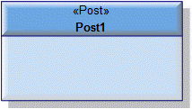
For a Resource Connector: the Resource Role elements that own the source and destination Resource Port elements must use an Organization, Post or Role Type as their type.
For a Service Channel: the Resource Role elements that own the source and destination Request and Service elements must use an Organization, Post or Role Type as their type.
On the Select Conveyed Classifier dialog, create or select the Exchange Element that is the Command element's conveyed classifier. On the context menu, click the command for the destination element.
To define that a Command is realized by a Resource Connector or Service Channel:
• Drag the Command from a Modeler pane to the Resource Connector or Service Channel on the diagram.
• Drag the Command element's conveyed classifier from a Modeler pane to the Resource Connector or Service Channel on the diagram. On the Select Command dialog, select the Command.
• Right-click the Resource Connector or Service Channel, point to Links, point to Realized, and then click Command. From the dialog, select the Command elements that are realized by the Resource Connector or Service Channel.
• Click the Control toolbar button, and then click the Resource Connector or Service Channel that realizes the Control:
For a Resource Connector: The Resource Role that owns the source Resource Port must use an Organization, Post or Role Type as its type. The Resource Role that owns the target Resource Port must use a Resource Artifact as its type.
For a Service Channel: The Resource Role that owns the source Request or Service must use an Organization, Post or Role Type as its type. The Resource Role that owns the target Request or Service must use a Resource Artifact as its type.
On the Select Type dialog, create or select the Exchange Element that is the Control element's conveyed classifier. On the context menu, irrespective of which command you click, the destination of the Control will be set to the Resource Role that uses a Resource Artifact as its type.
To define that a Control is realized by a Resource Connector or Service Channel:
• Drag the Control from a Modeler pane to the Resource Connector or Service Channel on the diagram.
• Drag the Control element's conveyed classifier from a Modeler pane to the Resource Connector or Service Channel on the diagram. On the Select Control dialog, select the Control.
• Right-click the Resource Connector or Service Channel that is to be realized, point to Links, point to Realized, and then click Control. From the dialog, select the Control elements that are realized by the Resource Connector or Service Channel.
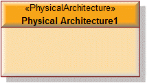
When you create an SV-2 Resource Communications Description from a Physical Architecture, Modeler does not add the owning Physical Architecture to the diagram.
To show the owning Physical Architecture on the diagram: right-click the background of the diagram, point to Populate, and then click Owner.
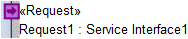
• Click the Request toolbar button, and then click the diagram owner or Resource Role element that is to own the Request. From the Select Type dialog, create or select the Service Interface that is the type of the Request, or create an untyped Request.
If the owner of the SV-2 Resource Communications Description is not shown on the diagram, create a Request on the diagram owner by clicking in free space.
• From an appropriate Modeler pane, locate the Service Interface that you want to use as the type of the Request, and then drag that Service Interface to the edge of the diagram owner or Resource Role element on the diagram. From the dialog, select Request, and then click OK.
If the owner of the SV-2 Resource Communications Description is not shown on the diagram, create a Request on the diagram owner by dragging the Service Interface to free space.
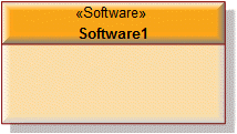
The diagram owner can be a Capability Configuration, Organization, Physical Architecture, Post, Resource Artifact, Role Type, Service Access or Software element.
Use Service Channel relationships to link the Request to other Request and Service elements.
When you create an SV-2 Resource Communications Description from a Resource Artifact, Modeler does not add the owning Resource Artifact to the diagram.
To show the owning Resource Artifact on the diagram: right-click the background of the diagram, point to Populate, and then click Owner.
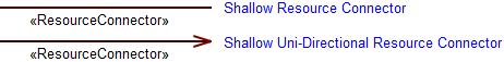
To create a Resource Connector: click the Shallow Resource Connector or Shallow Uni-Directional Resource Connector toolbar button, click the source Resource Port, and then click the destination Resource Port.
If you want to create a Resource Connector and connecting Resource Port elements in one operation, use the Resource Connector Complete toolbar button. On the Select Type dialog, select the type of the Resource Port elements.
To create a Resource Constraint: click the Resource Constraint toolbar button, and then click in free space on the diagram.
To apply a Resource Constraint to an element on the diagram: click the Note Link toolbar button, click the Resource Constraint, and then click the element to which the Resource Constraint applies.
You can apply a Resource Constraint to Capability Configuration, Organization, Physical Architecture, Post, Resource Artifact, Role Type, Service Access or Software elements.
• Click the Resource Interaction toolbar button, and then click the Resource Connector or Service Interface that realizes the Resource Interaction.
On the Select Conveyed Classifier dialog, create or select the Resource Interaction element's conveyed classifier, and from the context menu click the command for the destination element.
To define that a Resource Interaction is realized by a Resource Connector or Service Interface:
• Drag the Resource Interaction from a Modeler pane to the Resource Connector or Service Interface on the diagram.
• Drag the Resource Interaction element's conveyed classifier from a Modeler pane to the Resource Connector or Service Interface on the diagram. On the Select Resource Interaction dialog, select the Resource Interaction.
• Right-click the Resource Connector or Service Interface, point to Links, point to Realized, and then click Resource Interaction. From the dialog, select the Resource Interaction elements that are realized by the Resource Connector or Service Interface.
• Click the Resource Port toolbar button, and then click the diagram owner or Resource Role element that is to own the Resource Port. From the Select Type dialog, create or select the element that is the type of the Resource Role.
If the owner of the SV-2 Resource Communications Description is not shown on the diagram, create a Service on the diagram owner by clicking in free space.
• From an appropriate Modeler pane, locate the element that you want to use as the type of the Resource Port, and then drag that element to the edge of the diagram owner or Resource Role element on the diagram.
If the owner of the SV-2 Resource Communications Description is not shown on the diagram, create a Service on the diagram owner by dragging the type to free space.
The type of a Resource Port can be a Capability Configuration, Energy, Exchange Element, Geo Political Extent Type, Materiel, Organization, Physical Architecture, Post, Resource Artifact, Role Type, Service Access or Software element.
Use Resource Connector relationships to link the Resource Port to other Resource Port elements.
• Click the Resource Role toolbar button, and then click the diagram owner or Resource Role element that is to own the Resource Role. From the Select Type dialog, create or select the element that is the type of the Resource Role.
If the owner of the SV-2 Resource Communications Description is not shown on the diagram, create a Resource Role by clicking in free space.
• From an appropriate Modeler pane, locate the element that you want to use as the type of the Resource Role, and then drag that element to the diagram owner or Resource Role element on the diagram.
The type of a Resource Role can be a Capability Configuration, Organization, Physical Architecture, Post, Resource Artifact, Role Type, Service Access or Software element.
If the owner of the SV-2 Resource Communications Description is not shown on the diagram, create a Resource Role on the diagram owner by dragging the type to free space.
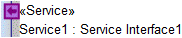
• Click the Service toolbar button, and then click the diagram owner or Resource Role element that is to own the Service. From the Select Type dialog, create or select the Service Interface that is the type of the Service.
If the owner of the SV-2 Resource Communications Description is not shown on the diagram, create a Service on the diagram owner by clicking in free space.
• From an appropriate Modeler pane, locate the Service Interface that you want to use as the type of the Service, and then drag that Service Interface to the edge of the diagram owner or Resource Role element on the diagram. From the dialog, select Service, and then click OK.
If the owner of the SV-2 Resource Communications Description is not shown on the diagram, create a Service on the diagram owner by dragging the Service Interface to free space.
The diagram owner can be a Capability Configuration, Organization, Physical Architecture, Post, Resource Artifact, Role Type, Service Access or Software element.
Use Service Channel relationships to link the Service to other Service and Request elements.
To create a Service Channel: click the Shallow Service Channel or Shallow Uni-Directional Service Channel toolbar button, click the source Request or Service, and then click the destination Request or Service.
If you want to create a Service Channel and connecting port elements (Request or Service elements) in one operation, use the Complete Service Channel toolbar button. Choose whether to create source and destination Request or Service elements, and then select the type of those elements.
To create a Service Policy: click the Service Policy toolbar button, and then click in free space on the diagram.
To apply a Service Policy to an element on the diagram: click the Note Link toolbar button, click the Service Policy, and then click the element to which the Service Policy applies.
You can apply a Service Policy to Capability Configuration, Organization, Physical Architecture, Post, Resource Artifact, Role Type, Service Access or Software elements.

 .
.
 Command toolbar button, and then click the Resource Connector or Service Channel that realizes the Command:
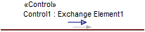
 Control toolbar button, and then click the Resource Connector or Service Channel that realizes the Control:
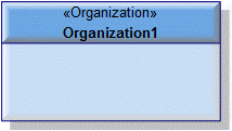
 Request toolbar button, and then click the diagram owner or Resource Role element that is to own the Request. From the Select Type dialog, create or select the Service Interface that is the type of the Request, or create an untyped Request.
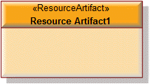
 Shallow Resource Connector or
  Shallow Uni-Directional Resource Connector toolbar button, click the source Resource Port, and then click the destination Resource Port.
 Resource Connector Complete toolbar button. On the Select Type dialog, select the type of the Resource Port elements.
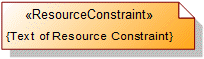
 Resource Constraint toolbar button, and then click in free space on the diagram.
 Note Link toolbar button, click the Resource Constraint, and then click the element to which the Resource Constraint applies.
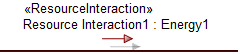
 Resource Interaction toolbar button, and then click the Resource Connector or Service Interface that realizes the Resource Interaction.
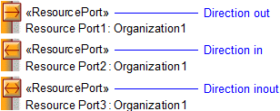
 Resource Port toolbar button, and then click the diagram owner or Resource Role element that is to own the Resource Port. From the Select Type dialog, create or select the element that is the type of the Resource Role.
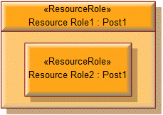
 Resource Role toolbar button, and then click the diagram owner or Resource Role element that is to own the Resource Role. From the Select Type dialog, create or select the element that is the type of the Resource Role.
 Service toolbar button, and then click the diagram owner or Resource Role element that is to own the Service. From the Select Type dialog, create or select the Service Interface that is the type of the Service.
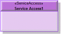
 Shallow Service Channel or
  Shallow Uni-Directional Service Channel toolbar button, click the source Request or Service, and then click the destination Request or Service.
 Complete Service Channel toolbar button. Choose whether to create source and destination Request or Service elements, and then select the type of those elements.
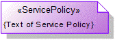
 Service Policy toolbar button, and then click in free space on the diagram.